
Sensor network long-distance charging and power supplying system based on laser light source

A sensor network and laser light source technology, applied in the field of sensor networks, can solve the problems of wireless sensor networks that are not suitable for random distribution of nodes, difficult long-distance transmission of energy, and attenuation of transmission efficiency, so as to improve remote photoelectric conversion efficiency and output power , high energy transmission efficiency, and the effect of reducing peak brightness

Inactive Publication Date: 2012-10-03
SOUTHEAST UNIV
View PDF4 Cites 6 Cited by
  • Summary
  • Abstract
  • Description
  • Claims
  • Application Information

AI Technical Summary

Problems solved by technology

However, whether it is a small electrical appliance or a large electric vehicle, the currently widely used charging and supply method is electromagnetic near-field coupling. The transmitting coil and the receiving coil are close to each other (generally millimeter or centimeter level), which is obviously not suitable for wireless networks with randomly distributed nodes. Sensor Networks
Moreover, wireless charging and power supply equipment for electric vehicles and home appliances generally have high power, and sensor nodes are all low-power electronic devices, so they are not suitable for charging and supplying nodes.
Magnetic resonance wireless charging power supply method is difficult to transmit energy over long distances, and the transmission efficiency decays exponentially with distance
The microwave wireless charging power supply method is greatly affected by environmental factors, and it is difficult to effectively transmit energy

Method used


Image

  • Sensor network long-distance charging and power supplying system based on laser light source
  • Sensor network long-distance charging and power supplying system based on laser light source
  • Sensor network long-distance charging and power supplying system based on laser light source

Examples


Embodiment Construction

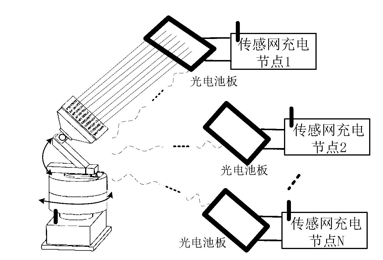
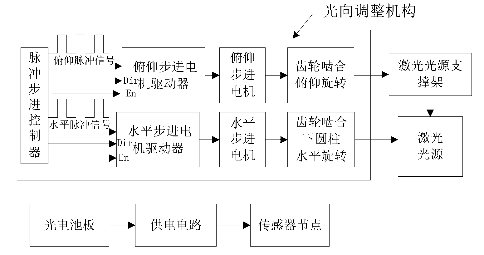
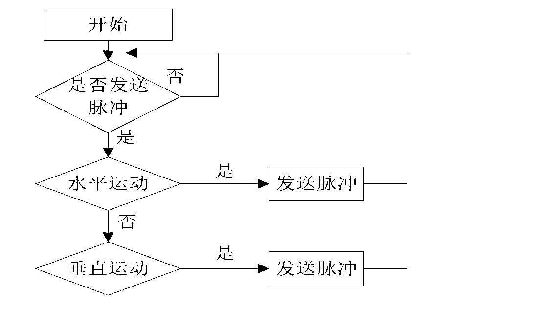
[0032] see figure 1A remote charging and supplying system is composed of a charging and supplying master with a laser light source and a light direction adjustment mechanism and a wireless sensor network node charging and supplying slave composed of multiple sensor networks. see figure 2 and Figure 18 The charging and power supply host includes a laser light source and a light direction adjustment mechanism. The laser light source is N×M laser heads distributed in a rectangular array, and the light directions of each laser head are parallel; the light direction adjustment mechanism includes a pulse stepping controller, a pitch stepping motor, Pitching stepping motor driver, horizontal stepping motor and horizontal stepping motor driver, pulse stepping controller under the command of the controller, respectively output pulse signals to pitching stepping motor driver and horizontal stepping motor driver, pitching stepping motor driver Drive the pitch stepping motor, the hori...


PUM


Abstract

The invention discloses a sensor network long-distance charging power-supply system based on a laser light source. The sensor network long-distance charging power-supply system comprises a charging power-supply main machine and a sensor network node charging power-supply auxiliary machine, wherein the charging power-supply main machine comprises the laser light source and a light direction adjusting mechanism which comprises a pulse step controller, a pitching stepping motor, a pitching stepping motor driver, a horizontal stepping motor and a horizontal stepping motor driver; the pulse step controller respectively outputs a pulse signal to the pitching stepping motor driver and the horizontal stepping motor driver so as to drive the pitching stepping motor and the horizontal stepping motor; the output shafts of the pitching stepping motor and the horizontal stepping motor adjust the pitching and horizontal positions of the laser light source through a gear transmission mechanism, each node charging power-supply auxiliary machine comprises a nodal processor, a photocell plate, a voltage detection circuit, a voltage-stabilizing module and a power supply circuit; and the photocell plates receive laser energy so as to form a charging power supply through the voltage-stabilizing modules, and carry out charging power supply for a sensor network node for a power supply circuit.

Description

technical field [0001] The invention relates to wireless charging and power supply technology for electrical equipment, in particular to a sensor network remote charging and power supply system based on a laser light source, which belongs to the technical field of sensor networks. Background technique [0002] The rapid development of sensor technology, electronic technology, wireless communication technology and low-power embedded technology has given birth to Wireless Sensor Networks (WSN), and with its low power consumption, low cost, distributed and self-organizing characteristics Bringing about a revolution in information perception. A wireless sensor network is a network composed of sensor nodes, which can monitor, perceive and collect various information (such as light intensity, temperature, humidity, noise and harmful gas concentration) of objects of interest to observers in the node deployment area in real time. and other physical phenomena), and the information i...

Claims


Application Information

Patent Timeline
Patent Type & Authority Applications(China)
IPC IPC(8): H02J7/00H02N6/00H02S40/20
CPCY02E10/50
Inventor 吴剑锋李建清徐高志罗堪杨华
Owner SOUTHEAST UNIV
Learn More