
Compact power divider

A power divider, compact technology, applied in the direction of waveguide devices, electrical components, connecting devices, etc., can solve the problems of small insertion loss, complicated manufacturing process, poor isolation, etc., and achieve good isolation, phase and amplitude balance Good, the effect of reducing assembly errors

Inactive Publication Date: 2012-10-03
成都赛纳赛德科技有限公司
View PDF3 Cites 5 Cited by
  • Summary
  • Abstract
  • Description
  • Claims
  • Application Information

AI Technical Summary

Problems solved by technology

The cavity waveguide power divider has small insertion loss and good amplitude balance, but its disadvantages are poor isolation and complicated manufacturing process

Method used


Image

  • Compact power divider
  • Compact power divider
  • Compact power divider

Examples


Embodiment

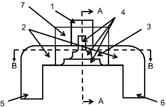
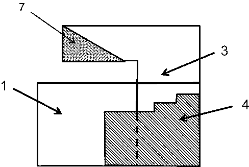
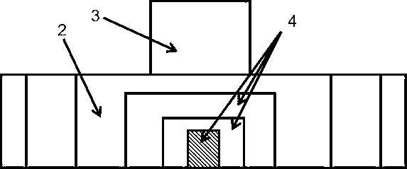
[0023] Such as figure 1 , figure 2 As shown, the present invention sets the axis of the first output rectangular waveguide 2, the axis of the input rectangular waveguide 1, and the axis of the second output rectangular waveguide 3 into a structure in which the structural axes are perpendicular to each other in a two-dimensional three-dimensional space, which can solve the problem of amplitude The problem of good balance, meanwhile, the internal matching structure 4 can effectively ensure the problem of isolation, and in order to ensure the optimization of the effect, the matching structure 4 is processed by one-time milling. Therefore, a kind of compact power splitter, comprises mainly by outputting the first output rectangular waveguide 2, and the input rectangular waveguide 1 and the second output rectangular waveguide 3 connected with the first output rectangular waveguide 2, the first output rectangular waveguide of the output A matching structure 4 is arranged inside th...


PUM


Abstract

The invention discloses a compact power divider which mainly comprises a first output rectangular waveguide, an input rectangular waveguide which is connected with the first output rectangular waveguide and a second output waveguide, wherein a matching structure is arranged in the first output rectangular waveguide, and partially extends into the input rectangular waveguide, one end of the second output rectangular waveguide, which is far away from the matching structure, is bent around the axis direction of the first output waveguide by 90 degrees, and wave-absorbing materials are arranged at the bending part of the second output rectangular waveguide. The compact power divider has the beneficial effects that the compact power divider is simple to process, the matching structure and a magnetic T can be processed through one milling, so the assembly error during the assembly matching result is reduced, the compact power divider has a compact structure, the phase and amplitude balance of an output port is good, and isolated ports are well isolated from each other.

Description

technical field [0001] The invention relates to a power divider, in particular to a compact power divider. Background technique [0002] Power dividers and combiners are important components in microwave systems, which are used to distribute transmission power to different loads, or combine different power into one circuit to obtain greater power. The performance of the microwave power divider, such as insertion loss, isolation, phase balance and amplitude balance, will have an important impact on the performance of the entire system. At present, the common power divider is a distributed parameter power divider using microstrip line or cavity waveguide. The cavity waveguide power divider has small insertion loss and good amplitude balance, but its disadvantages are poor isolation and complicated manufacturing process. Contents of the invention [0003] The purpose of the present invention is to provide a magic T power splitter with simple processing, good isolation and c...

Claims


Application Information

Patent Timeline
IPC IPC(8): H01P5/16H01P5/20
Inventor 王清源谭宜成文松
Owner 成都赛纳赛德科技有限公司
Learn More