
Movable electrode (cathode) for stainless steel inner tube electropolishing

An electropolishing, stainless steel tube technology, applied in the electrolysis process, electrolysis components, etc., can solve the problems of gas not in time, high viscosity, small current flow area, etc.

Inactive Publication Date: 2012-10-03
SHANGHAI MINOW SMOOTH IND TRADE
View PDF0 Cites 13 Cited by
  • Summary
  • Abstract
  • Description
  • Claims
  • Application Information

AI Technical Summary

Problems solved by technology

If the current is increased by increasing the voltage, if the cross-sectional area is constant, the flowing current is too large, and it is easy to burn the auxiliary electrode.
[0006] 2. The range of stainless steel tubes that can be processed is narrow: Due to the limitation of the inner diameter of stainless steel, and considering the distance requirements of the cathode and anode of electrolytic polishing, the auxiliary electrode (cathode) inserted into the tube will be very small. For some stainless steel with diameters of millimeters For tubes, a cathode with a diameter too small cannot be inserted into a stainless steel tube with a length of six meters, and because the diameter is small, the current flow area will be small, and a large current cannot pass through. Often, the two ends of the stainless steel tube inlet can be electrolytically polished, but The middle of the tube cannot be reached by current, without any polishing effect
[0008] Due to the very high density (about 1.75) and high viscosity of the electrolytic polishing liquid, coupled with the small space in the stainless steel tube, a lot of gas is generated during processing, which leads to the gas not being discharged from the tube in time, which seriously affects the electrolytic polishing effect. There are often white spots in the tube, which is the result of gas accumulation here, which has not been electropolished.
[0009] 4. Unstable polishing quality: due to the defects of the electric (cathode) electrode for electrolytic polishing of the stainless steel inner tube, the polishing quality cannot be guaranteed due to the above reasons: if the current is not large enough, the brightness will be poor; if the gas cannot be discharged in time, There will be parts that cannot be polished; the application range of processing stainless steel pipes is limited, and some stainless steel pipes with very long lengths and small diameters cannot be processed according to
[0010] 5. Low production efficiency and automation: The traditional auxiliary electrode installation is manual operation; the rationality of the installation is all determined by the operator, skilled workers and unskilled workers, due to experience, the installation is different, electrolytic The quality of polishing will also vary
Moreover, the labor intensity is high and the difficulty is high, especially the electrolytic polishing liquid is generally an acidic potion, and the direct operation of personnel has a high degree of work risk.
[0011] Through the above analysis, it can be seen that the existing auxiliary electric (cathode) electrodes for electropolishing in stainless steel tubes all have "small electropolishing current, narrow range of processing stainless steel tubes, more gas generated during electropolishing, unstable and low polishing quality, and low production efficiency. Low degree of automation" and many other problems
Therefore, the quality processed by the existing domestic electrolytic polishing equipment for stainless steel pipes cannot compete with imported stainless steel electrolytic polishing pipes, and cannot compete with them.

Method used


Image

  • Movable electrode (cathode) for stainless steel inner tube electropolishing
  • Movable electrode (cathode) for stainless steel inner tube electropolishing
  • Movable electrode (cathode) for stainless steel inner tube electropolishing

Examples


Embodiment Construction

[0029] In order to be able to understand the technical content of the present invention more clearly, the following embodiments are specifically described in detail.

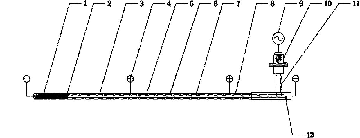
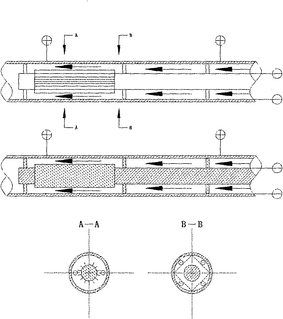
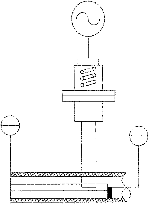
[0030] See Figure 1 ~ Figure 4 As shown, the movable auxiliary electric (cathode) electrode for electrolytic polishing of the stainless steel inner tube of the present invention includes a movable auxiliary electric (cathode) electrode 7, a pulling device 11, and a PID fuzzy automatic control system; the movable auxiliary electric (cathode) ) Pole 7 includes auxiliary electric (cathode) pole 1, support frame 6, connecting rod 3; said pulling device 11 includes stepping motor 10, frequency converter 11, limit switch 12, voltmeter, ammeter, overcurrent voltage protection device , Emergency stop button, etc.; the manual automatic control system includes PLC, data collector, frequency converter, PID fuzzy control software, manual automatic switch button, etc.; the auxiliary electric (cathode) pole 1 is located in fron...


PUM


Abstract

The invention relates to a movable electrode (cathode) for stainless steel inner tube electropolishing processing; the electrode is movable, and the moving speed can be adjusted continuously according to the processing quality and requirements; materials with good conductivity performance are selected, and have a length of about 100 mm-200 mm; an insulation ring is mounted between the electrode and a stainless steel tube inner wall; the movable electrode is fixed at a center position of a shaft of the stainless steel tube so as to allow the distance between the cathode and an anode (the stainless steel tube) to be the same; and thus the processed electropolishing quality is consistent; the copper electrode is not cylinderical, but has a sheet structure, which increases the conductive area of the cathode and improves the electropolishing quality. Adequate intervals are left between the movable electrode (cathode) and the stainless steel tube inner wall to be processed, and thus the flow of electropolishing liquid is not interfered; on one hand, the discharge of gas generated during electropolishing is quite facilitated; on the other hand, wastes generated during electropolishing is taken away timely. Both length and size ranges of stainless steel tubes to be processed are enlarged greatly, and the quality is ensured.

Description

Technical field [0001] The invention relates to the technical field of electrolytic polishing of stainless steel inner tubes, in particular to a movable auxiliary electric (cathode) electrode used for electrolytic polishing of stainless steel inner tubes. The moving speed can be manually adjusted according to actual needs. Background technique [0002] The existing stainless steel inner tube is often electropolished according to actual needs. Due to the different calibers and lengths of stainless steel tubes, it is impossible to electropolish the inner wall of the stainless steel tube without placing an auxiliary electrode in the tube. [0003] The electric (cathode) electrode for electrolytic polishing of the existing stainless steel tube inner tube generally adopts a fixed method. An auxiliary electrode is inserted into the stainless steel tube so that the inner wall of the stainless steel tube and the auxiliary electrode are filled with electrolytic polishing liquid. The stainle...

Claims


Application Information

Patent Timeline
IPC IPC(8): C25F3/24C25F7/00
Inventor 王琪
Owner SHANGHAI MINOW SMOOTH IND TRADE
Learn More