
Mounting structure for solid-state light sources

A technology of installation structure and solid-state light source, applied in the direction of light source, point light source, light source fixation, etc., can solve the problem that CoB technology cannot solve the problem of integration of light source and control/driver level, achieve good sound insulation and ensure high reliability.

Active Publication Date: 2012-09-26
OPTOTRONIC GMBH
View PDF6 Cites 1 Cited by
  • Summary
  • Abstract
  • Description
  • Claims
  • Application Information

AI Technical Summary

Problems solved by technology

[0006] The inventors have noticed that in the latest generation of SSL applications, CoB technology does not solve the problem of integrating the light source with the control / driver stage

Method used


Image

  • Mounting structure for solid-state light sources
  • Mounting structure for solid-state light sources
  • Mounting structure for solid-state light sources

Examples


Embodiment Construction

[0027] In the following description, numerous specific details are described to provide a fuller understanding of the embodiments. The described embodiments may be practiced without one or more of these specific details, or the described embodiments may be practiced using other methods, components, materials, or the like. In other instances, known structures, materials, or operations are not specifically shown or described so that aspects of the described embodiments may be more clearly understood.

[0028] "One embodiment" mentioned in the context of this specification means that a specific configuration, structure or characteristic described with respect to the embodiment is included in at least one embodiment. Thus, phrases such as "in one embodiment," which may appear in multiple places in this specification, do not necessarily refer to the same embodiment. Furthermore, particular forms, structures or characteristics may be combined in any suitable form into one or more e...


PUM


Abstract

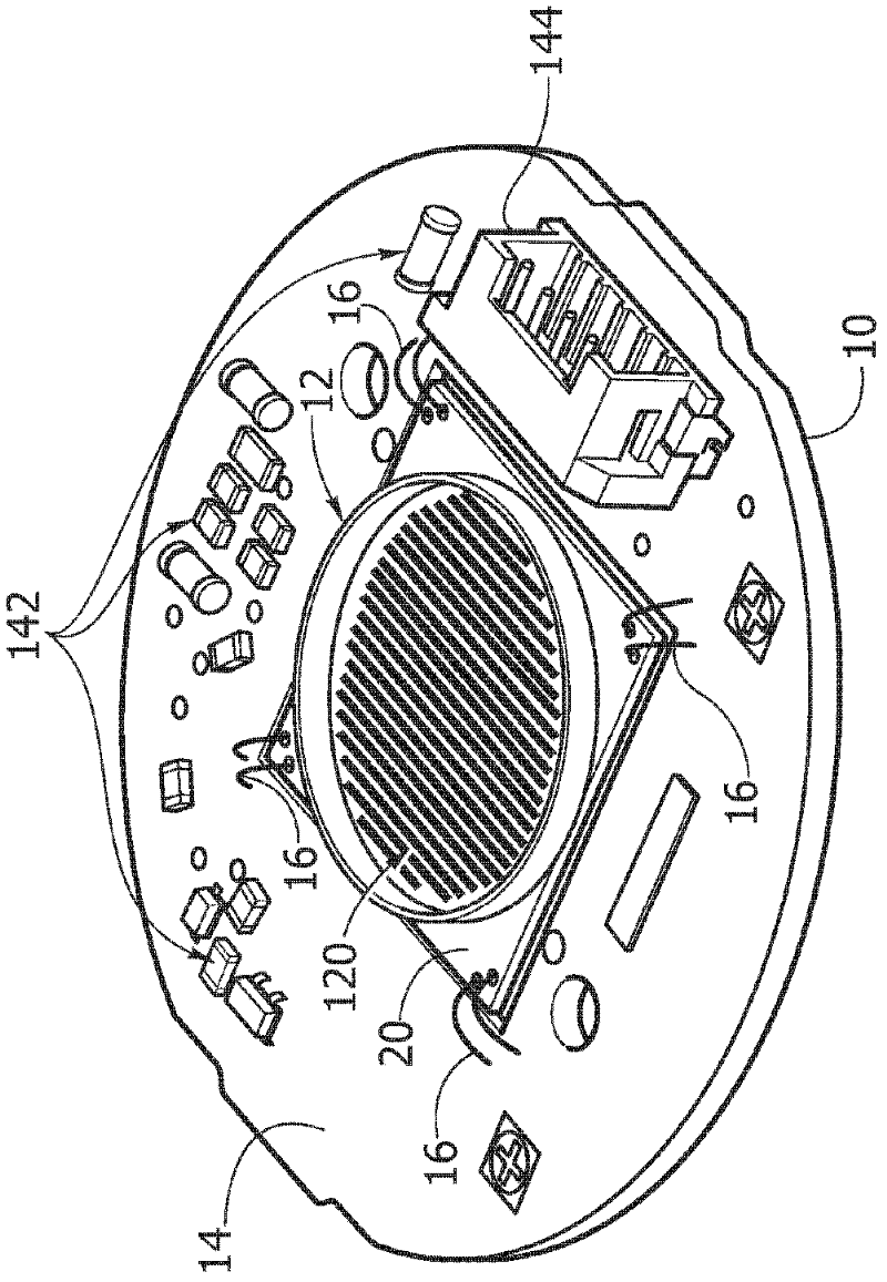
A mounting structure for solid-state light sources, for example of the LED type (120), comprises: - a support board (10), - a submount (20) mounted on said support board (10) and having at least one solid-state light radiation source (120) mounted thereon, - a drive board (14) carrying drive circuitry (142) for the light radiation source (120), the aforementioned drive board being mounted on the support board (10) and extending peripherally with respect to the aforementioned submount (20), - electrical interface connections (16, 162) between the submount (20) and the drive board (14) for connecting the light radiation source (120) to the drive circuitry (142), and - mechanical and thermal interface connections (22; 162, 220) between the submount (20) and the support board (10).

Description

technical field [0001] The invention relates to a solid-state light source. [0002] In various embodiments, the description may refer to light sources based on the use of light emitting diodes (LEDs). Background technique [0003] In the manufacture of solid state light sources (currently known as the solid state lighting or SSL industry), a technology known as "Chip on Board" or CoB is increasingly used. This technology envisages the direct integration of LED dies onto a board acting as a submount or standoff, thereby avoiding the use of conventional packaging. Thus, for example, this may also enable improved solutions in terms of i) better thermal performance; ii) better optical coupling; and iii) higher integration. In this connection, attempts have been made to implement highly integrated (intelligent) functions in so-called light engines in order to be able to combine an optimal efficiency level of light irradiation with the ability to control and manage light irradi...

Claims


Application Information

Patent Timeline
Patent Type & Authority Applications(China)
IPC IPC(8): F21V19/00F21Y101/02
CPCH05K1/021H05K1/0203F21K9/00H05K2201/10106F21Y2101/02F21V23/005H05K1/141H05K3/0061F21V19/005F21V23/006F21V29/70F21Y2115/10F21V23/02
Inventor 京特·赫策尔休伊·林·李托马斯·普罗伊施尔彼得·萨克森韦格洛伦佐·罗伯托·特雷维萨内洛史蒂文·韦策尔
Owner OPTOTRONIC GMBH
Learn More