
Lamp

一种灯具、灯罩的技术,应用在具有散热功能的灯具领域,能够解决除尘便利性不佳、制造不便等问题,达到增加组装便利性、提升使用寿命、提升散热效果的效果

Inactive Publication Date: 2012-09-19
SUNONWEALTH ELECTRIC MACHINE IND
View PDF8 Cites 4 Cited by
  • Summary
  • Abstract
  • Description
  • Claims
  • Application Information

AI Technical Summary

Problems solved by technology

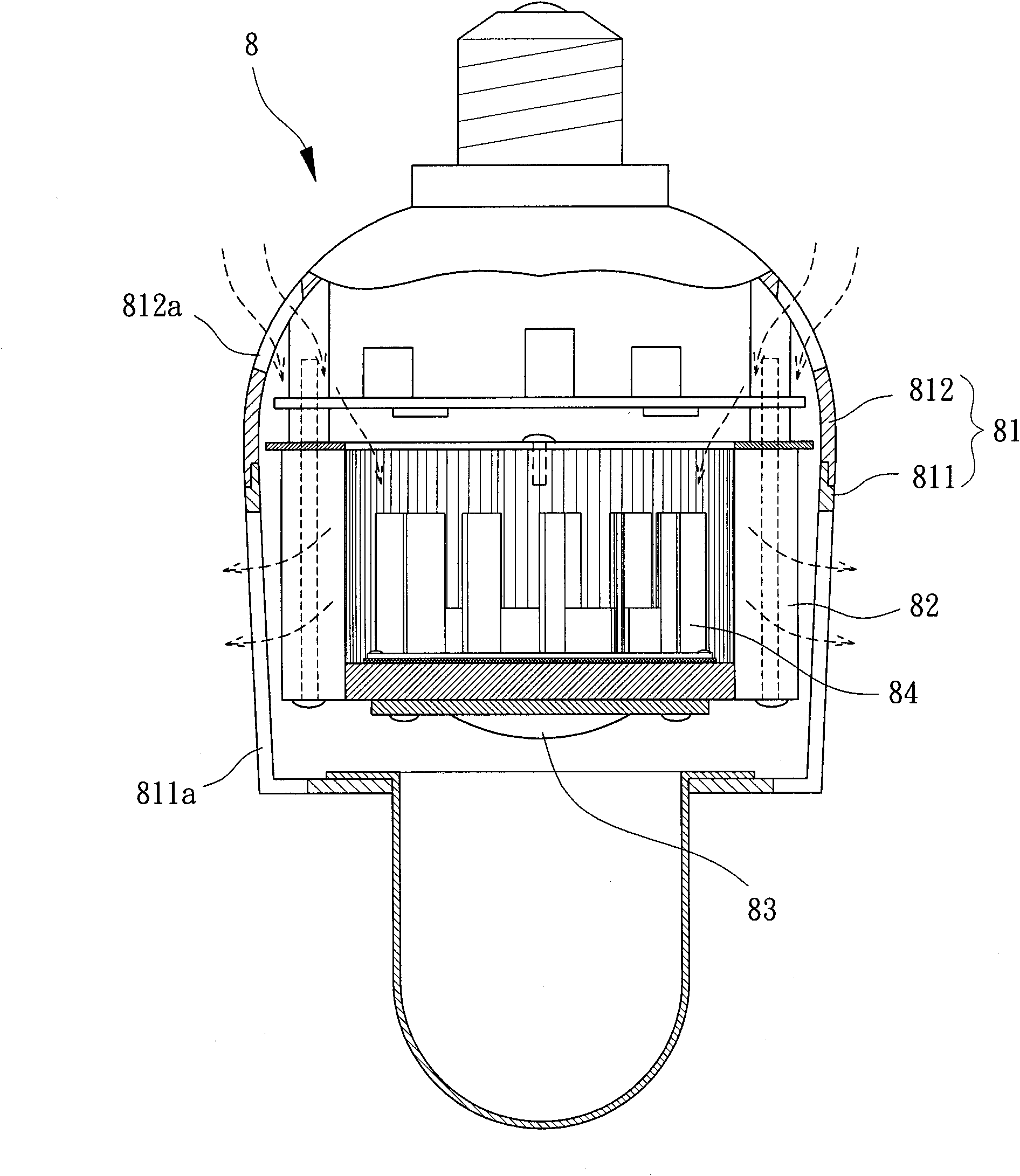
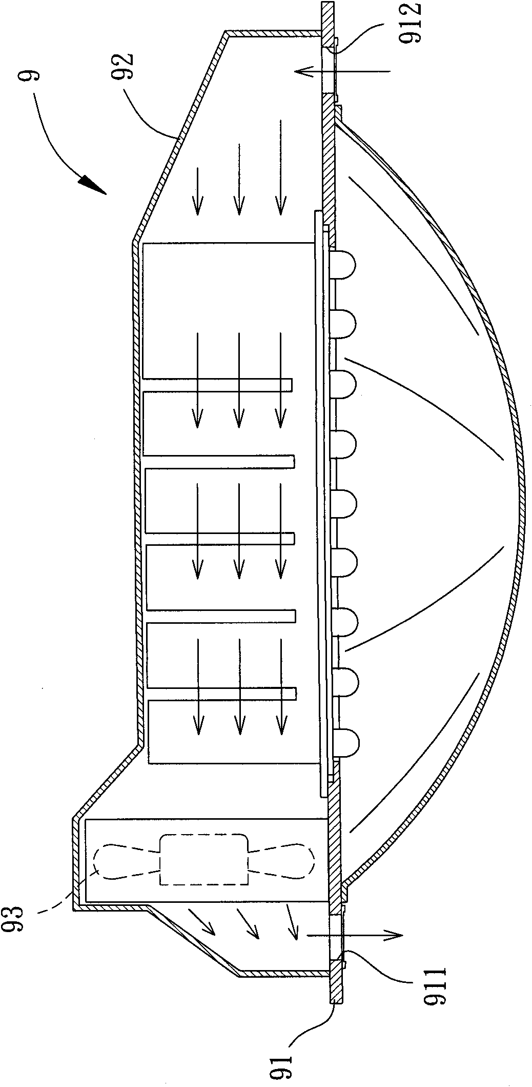
[0009] However, the fan 93 of the existing lamp 9 is also arranged between the first ventilating portion 911 and the second ventilating portion 912, therefore, the existing lamp 8 also has disadvantages such as poor dust removal convenience as disclosed above.
Furthermore, the lamp substrate 91 of the existing lamp 9 must be additionally provided with a first ventilation portion 911 and a second ventilation portion 912, which also causes a lot of inconvenience in manufacture.

Method used


Image

  • Lamp
  • Lamp
  • Lamp

Examples


Embodiment Construction

[0102] In order to make the above-mentioned and other objects, features and advantages of the present invention more comprehensible, the preferred embodiments of the present invention are specifically cited below, together with the accompanying drawings, as follows:

[0103] Please refer to Figure 4 , 5 As shown in and 6 , the lamp 1 of the first embodiment of the present invention at least includes a heat spreading element 11 , a light emitting module 12 , a housing 13 and a cooling fan 14 . Wherein the light-emitting module 12 is combined with the heat spreader 11; the housing 13 is also combined with the heat spreader 11 to cooperate with the heat spreader 11 to form a structural design for air flow; the cooling fan 14 is combined with the inside of the shell 13 , to provide a predetermined conduction heat dissipation function.

[0104] The heat spreader 11 is a component made of heat-conducting material, and the heat spreader 11 can be designed in various geometric shap...


PUM


Abstract

A lamp includes a heat conducting member, a light-emitting module, a housing and a cooling fan. The heat conducting member has a first face and a second face opposite to the first face. The light-emitting module is coupled with the first face. The housing is coupled with the heat conducting member and has a terminal opening, wherein first and second air-guiding openings are formed between the terminal opening and the heat conducting member. The housing has an inner circumferential wall. An air-flowing room is formed between the inner circumferential wall and the second face. The air-flowing room communicates with the first air-guiding opening and the second air-guiding opening. The cooling fan is disposed at the first or second air-guiding opening. Via the above structure, cooling effect can be improved, assembly convenience, dedusting convenience, and processing convenience are improved, manufacture cost is reduced and service lifetime of the lamp is improved.

Description

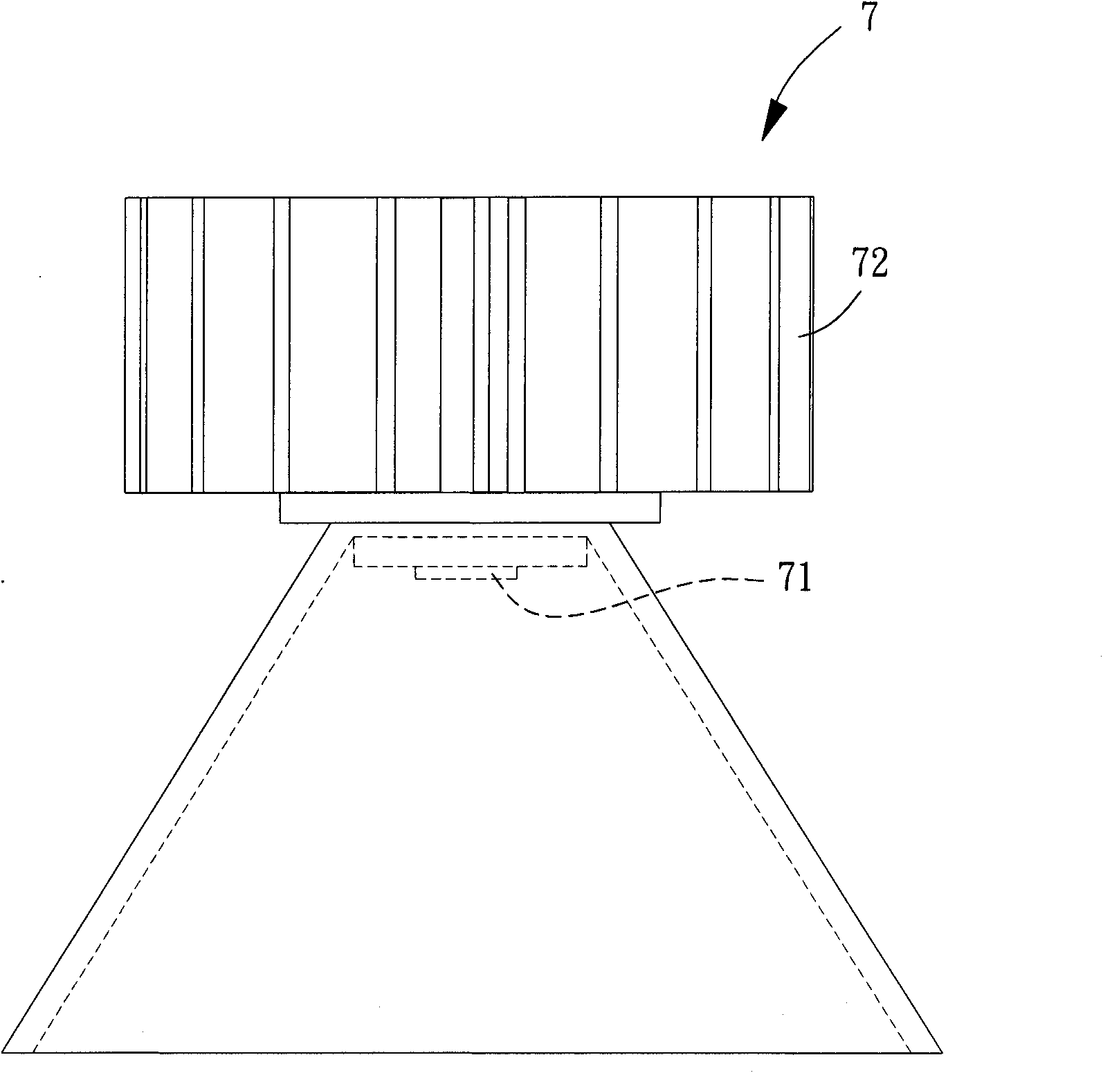
technical field [0001] The invention relates to a lamp, especially a lamp with heat dissipation function. Background technique [0002] Please refer to figure 1 As shown, the existing lamp 7 mainly has a light emitting module 71, and the light emitting module 71 is used to project light to achieve the purpose of lighting. However, when the light-emitting module 71 generates high heat due to power-on, if the existing lamp 7 does not have good cooling measures, it may cause the existing lamp 7 to not work normally and reduce its service life. Therefore, the light-emitting module 71 of the existing lamp 7 is combined with a heat sink 72 so as to use the heat sink 72 to absorb the heat generated by the light-emitting module 71 due to power-on operation, thereby preventing the light-emitting module 71 from generating high heat during actual operation. [0003] However, although the above-mentioned existing lamp 7 can improve the service life of the light emitting module 71 by m...

Claims


Application Information

Patent Timeline
Patent Type & Authority Applications(China)
IPC IPC(8): F21S2/00F21V29/02F21V3/02
CPCF21S2/00F21V1/00F21V3/02F21V29/2293F21V29/02F21Y2101/02F21V29/83F21Y2115/10F21V29/67
Inventor 蔡期琮
Owner SUNONWEALTH ELECTRIC MACHINE IND
Learn More