
Laser heating rivetless riveting device

A technology of rivetless riveting and laser heating, applied in the field of rivetless riveting device and laser heating rivetless riveting device, can solve the problems of reducing deformation resistance, material breaking, reducing riveting force, frame rigidity, etc., to reduce deformation resistance , good quality, the effect of improving plastic deformation ability

Inactive Publication Date: 2012-09-19
JILIN UNIV
View PDF8 Cites 39 Cited by
  • Summary
  • Abstract
  • Description
  • Claims
  • Application Information

AI Technical Summary

Problems solved by technology

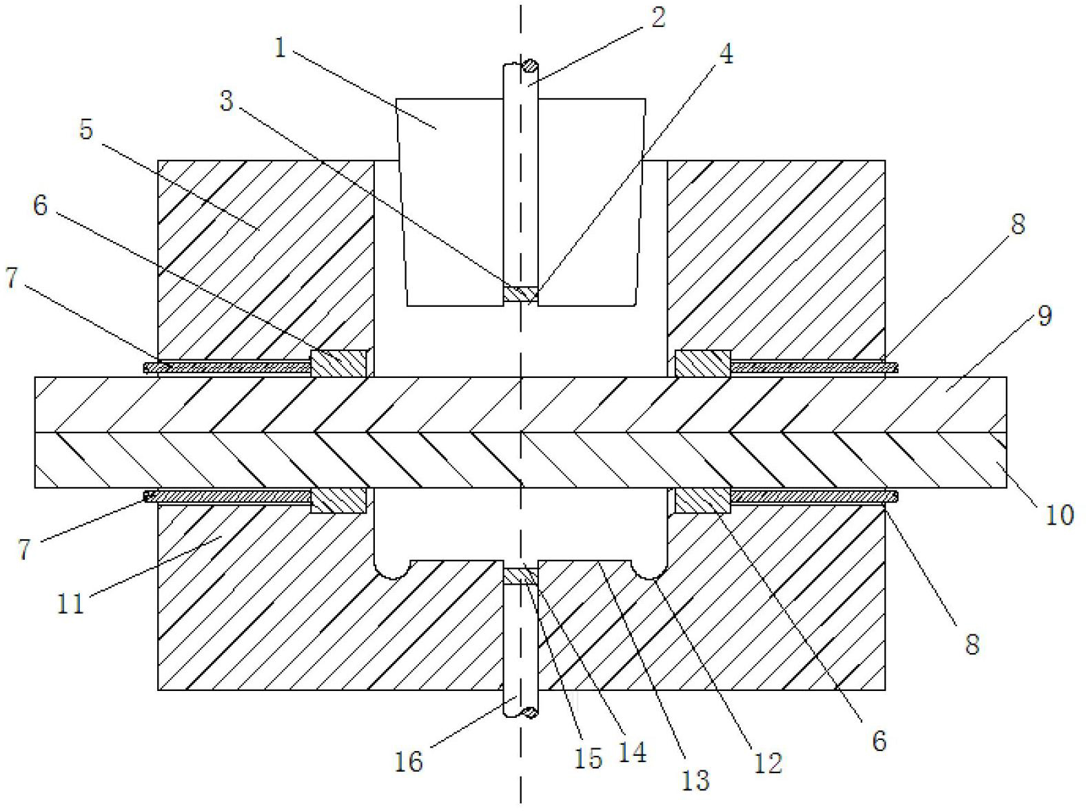
[0005] Aiming at the shortcomings of the current rivetless riveting technology, the present invention proposes a laser heating rivetless riveting device, which increases the formability of aluminum-magnesium alloy metal by introducing a laser heating temperature-controlled forming method, so as to solve the problem of poor formability of aluminum-magnesium alloy and other materials in the riveting process. At the same time, the laser heating and temperature-controlled forming method is used to reduce the yield limit of the material, reduce the deformation resistance when plastic deformation occurs, and reduce the requirements for riveting force and frame stiffness of riveting high-strength materials for riveting riveting equipment without rivets

Method used


Image

  • Laser heating rivetless riveting device
  • Laser heating rivetless riveting device
  • Laser heating rivetless riveting device

Examples


Embodiment Construction

[0022] The following is a detailed description of the embodiments of the present invention. This embodiment is implemented on the premise of the technical solution of the present invention. Detailed implementation modes and specific operation procedures are given. However, the protection scope of the present invention is not limited to the following embodiments. .

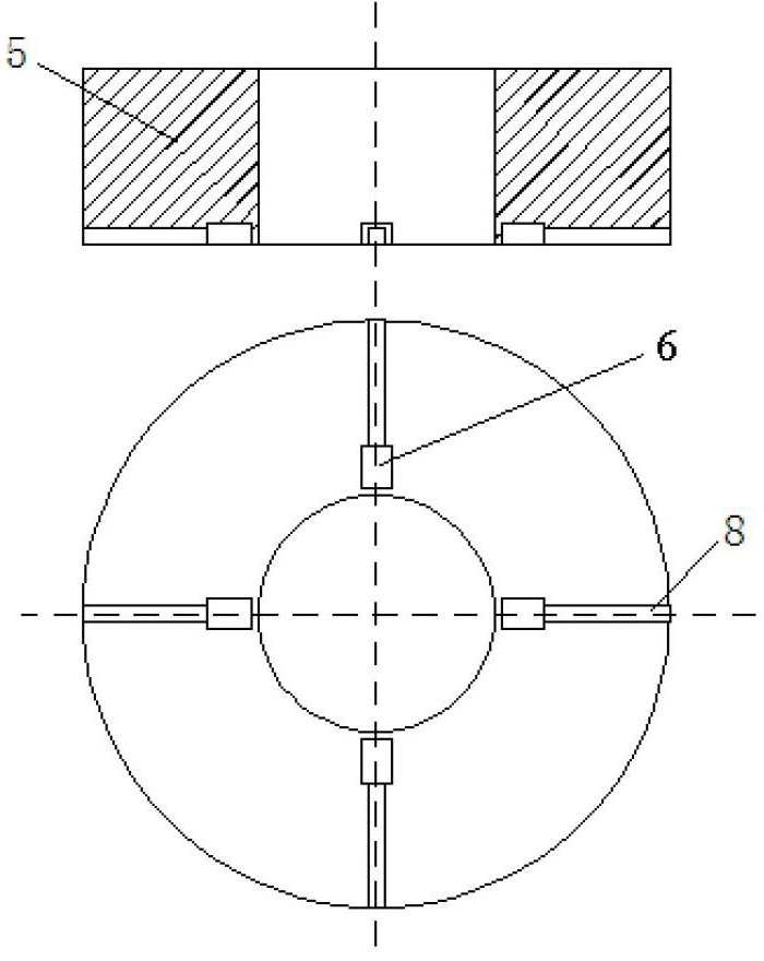
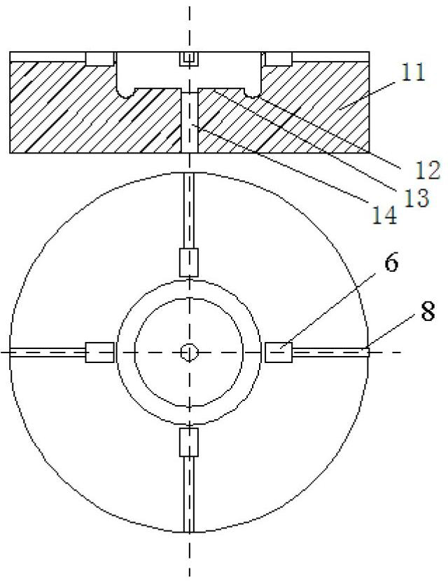
[0023] The invention includes a composite punch (1), a composite blank holder (5), a composite die (11) and a laser emission control part. The composite punch (1) is sleeved in the composite blank holder (5), and is arranged coaxially with the upper and lower plates (9), (10) and the composite die (11) from top to bottom.

[0024] The composite punch (1) has a round table structure with a hollow hole I (4) in the center. The diameter of the lower surface of the composite punch (1) is smaller than the diameter of the upper surface, and the outer surface of the composite punch (1) is provided with a certain draft angle A...


PUM


Abstract

The invention relates to a laser heating rivetless riveting device in the technical field of automobile manufacturing. The laser heating rivetless riveting device comprises a compound punch pin, a compound blank holder, a compound lower die and a laser control system, wherein, the compound punch pin is sheathed with the compound blank holder, and the compound punch pin, a workpiece and the lower die are arranged coaxially from top to bottom; hollow circular holes are formed at the center parts of the compound punch pin and the compound lower die; optical fiber tubes and concave lenses are arranged in the hollow circular holes; grooves are formed in the surfaces of the compound blank holder and the compound lower die in contact with a panel veneer, and are used for laying out thermistors that are lead wires; and the lead wires are connected with a laser control system. The laser heating rivetless riveting device heats a forming area of riveting material through laser before riveting forming so as to improve the forming performance of material, prevents fragile material from being easy to crack and fracture during the riveting process, reduces the plastic deformation resistance of material at the same time, enables the panel veneer to deform fully during the forming process, is easy to get a rivet joint with better quality, and reduces the requirements on riveting force and rigidity of riveting equipment at the same time along with the reduction of plastic deformation resistance of material.

Description

Technical field [0001] The invention relates to a rivetless riveting device in the technical field of automobile manufacturing, in particular to a laser heating rivetless riveting device. technical background [0002] The development of the automobile industry and the increasingly fierce contradiction between the world’s energy and environmental issues have promoted the development of the concept of automotive lightweighting. Under this concept, aluminum alloys and magnesium alloys are increasingly used in applications due to their low density and good corrosion resistance. In the automobile industry, high-strength steel and carbon fiber materials have high specific strength and are also widely used in car bodies. Because aluminum-magnesium alloy has high thermal conductivity and the surface is easy to oxidize, it is difficult to realize the connection between aluminum-magnesium alloy sheets by the traditional spot welding connection process; and the new structure often requires ...

Claims


Application Information

Patent Timeline
IPC IPC(8): B21D39/02B21D37/16B21D37/10
CPCB21J15/025B21J15/08
Inventor 庄蔚敏刘学成陈延红于皖东梁丽丽曹德闯
Owner JILIN UNIV
Learn More