
Incineration treatment device for nitrogen-containing organic wastes and incineration treatment process

An organic waste and treatment device technology, applied in incinerators, combustion methods, combustion types, etc., can solve the problem of uneven distribution of flow field and temperature field in the furnace, low nitrogen oxide emission concentration efficiency, thermal nitrogen oxides There are many problems, to achieve the effect of reducing the generation of thermal nitrogen oxides, reducing temperature, reducing investment costs and operating costs

Active Publication Date: 2012-08-22
天津辰创环境工程科技有限责任公司
View PDF5 Cites 16 Cited by
  • Summary
  • Abstract
  • Description
  • Claims
  • Application Information

AI Technical Summary

Problems solved by technology

[0003] At present, in the domestic organic waste incineration treatment industry, due to the diversification of waste types, it is a difficult problem for the selection and arrangement of burners. Insufficient atomization often occurs, easy to block, and the distribution of flow field and temperature field in the furnace is uneven, resulting in organic matter. It cannot be completely decomposed, and more thermal nitrogen oxides are produced
And there are problems such as the inefficiency of reducing the emission concentration of nitrogen oxides by using air in the exhausted flue gas or only using a single selective redox method

Method used


Image

  • Incineration treatment device for nitrogen-containing organic wastes and incineration treatment process
  • Incineration treatment device for nitrogen-containing organic wastes and incineration treatment process
  • Incineration treatment device for nitrogen-containing organic wastes and incineration treatment process

Examples


Embodiment Construction

[0021] The present invention will be described in further detail below in conjunction with the accompanying drawings.

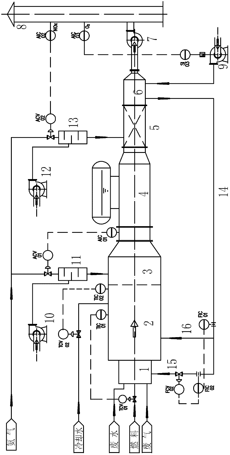
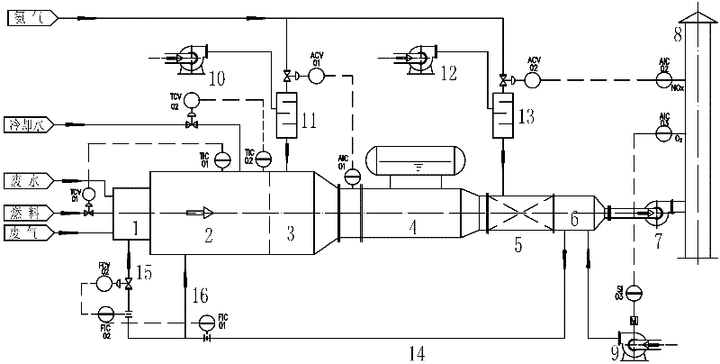
[0022] As shown in the accompanying drawings, the present invention is used for the incineration treatment device of nitrogen-containing organic waste, including a burner 1, a thermal oxidation furnace 2, a waste heat boiler 4, a selective catalytic reduction SCR processor 5, and an air preheater 6 connected in series. , an induced draft fan 7, a chimney 8 and a furnace pressure control circuit, the furnace pressure control circuit includes a pressure measuring point arranged at the front portion of the furnace of the thermal oxidation furnace 2 and a variable frequency motor connected with the induced draft fan 7 to form , adjust the frequency of the induced draft fan motor through this pressure measuring point, so as to ensure that the furnace has a certain negative pressure. The tail of the thermal oxidation furnace 2 is provided with a selective non-catal...


PUM


Abstract

The invention discloses an incineration treatment process for nitrogen-containing organic wastes, which includes: a, sending wastes into an incinerator to incinerate at a high temperature and maintaining the incineration temperature by injecting after-burning fuel; b, injecting combustion-supporting air which is divided into primary air and secondary air according to a certain proportion into a fire chamber for supporting combustion; c, injecting reducing agents to the tail of a hot oxidation furnace and reducing part of NOx in flue gas by the SNCR (selective non-catalytic reduction) method; d, leading high-temperature flue gas from the hot oxidation furnace into a waste heat boiler to recover part of heat; e, leading the flue gas from the waste heat boiler into an SCR(selective catalytic reduction) treater to reduce content of NOx in flue gas further; and f, further recovering afterheat of flue gas by the aid of an air preheater arranged at the downstream of the SCR treater and then discharging flue gas through a chimney. The incineration treatment process is simple and low in cost for incineration of organic wastes, denitration efficiency can be guaranteed by a two-stage denitration process, emission standards can be met, afterheat of flue gas can be recovered, and accordingly the incineration treatment process can be applied to the similar organic waste treatment projections in the chemical industry.

Description

technical field [0001] The invention belongs to the treatment technology of nitrogen-containing waste in the chemical industry, and in particular relates to an incineration treatment of organic waste with a certain calorific value, and adopts a flue gas denitrification method to remove NOx, so that the flue gas can be discharged up to the standard. Background technique [0002] Due to insufficient anticipation and poor prevention of the negative impact of human beings on highly developed industries, three global crises have resulted: resource shortage, environmental pollution, and ecological destruction. Humans continue to discharge pollutants into the environment. When the discharged substances exceed the self-purification capacity of the environment, adverse changes in environmental quality will occur, endangering human health and survival, and environmental pollution occurs. Environmental pollution will cause direct damage and impact on the ecological system, such as des...

Claims


Application Information

Patent Timeline
IPC IPC(8): F23G5/00F23G5/44F23G5/50
Inventor 侯国华那永新李梦凯杜庆丰
Owner 天津辰创环境工程科技有限责任公司
Learn More