Novel knotted reactor (KR) desulfurization stirring method

A technology of agitator and stirring paddle, applied in the field of iron and steel metallurgy, can solve the problems of insufficient dynamic conditions of molten iron, poor dispersion effect of desulfurizing agent, short service life of stirring paddle, etc. the effect of strength

Inactive Publication Date: 2012-08-22
LAIWU IRON & STEEL GRP
View PDF4 Cites 15 Cited by
  • Summary
  • Abstract
  • Description
  • Claims
  • Application Information

AI Technical Summary

Problems solved by technology

[0007] The purpose of the present invention is to overcome the problems of poor dispersion effect of desulfurizing agent, insufficient dynamic conditions of hot metal, and short service life of stirring blades existing in the existing method of mechanical stirring desulfurization of molten iron, and to provide a mechanical stirring desulfurization method of molten iron, which can improve the efficiency of desulfurization Dynamic conditions, improve the service life of the stirring paddle, and improve the desulfurization effect of mechanical stirring

Method used


Image

  • Novel knotted reactor (KR) desulfurization stirring method
  • Novel knotted reactor (KR) desulfurization stirring method

Examples


Embodiment 1

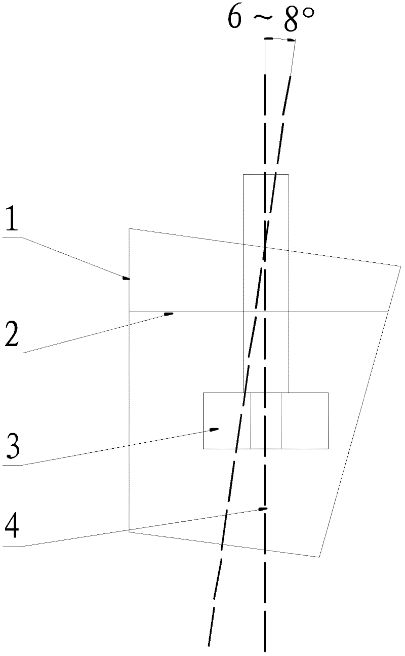
[0023] A stirring molten iron tank for rapid desulfurization, comprising a molten iron tank and an agitator, characterized in that the molten iron tank deviates from the vertical position by 6 to 8°; there is an agitator on the molten iron tank, and the stirring blade of the agitator is immersed in the iron in the molten iron tank in the water.

[0024] Such as figure 1 , the molten iron mechanical agitation desulfurization method of the present invention is that the molten iron tank 1 is tilted and placed, and its tilting angle deviates from the middle hammer axis line 4 of the tank body: 6 °, the stirring paddle 3 is immersed in molten iron for 1450 mm, and the agitator 3 The rotation and agitation of the molten iron make the desulfurization agent on the surface of the molten iron 2 involved in the molten iron, and a desulfurization reaction occurs to achieve the purpose of desulfurization.

Embodiment 2

[0026] Such as figure 1 , the molten iron mechanical agitation desulfurization method of the present invention is that the molten iron tank 1 is tilted and placed, and its tilting angle deviates from the middle hammer axis line 4 of the tank body: 7°, the stirring paddle 3 is immersed in the molten iron for 1200mm, and the agitator 3 The rotation and agitation of the molten iron make the desulfurization agent on the surface of the molten iron 2 involved in the molten iron, and a desulfurization reaction occurs to achieve the purpose of desulfurization.

Embodiment 3

[0028] Such as figure 1 , the molten iron mechanical agitation desulfurization method of the present invention is that the molten iron tank 1 is tilted and placed, and its tilting angle deviates from the middle hammer axis line 4 of the tank body: 8 °, the stirring paddle 3 is immersed in the molten iron for 1300mm, and the agitator 3 The rotation and agitation of the molten iron make the desulfurization agent on the surface of the molten iron 2 involved in the molten iron, and a desulfurization reaction occurs to achieve the purpose of desulfurization.


PUM


Abstract

The invention relates to a desulfurization method outside a molten iron furnace in front of a converter, in particular to a molten iron mechanical stirring desulfurization method of molten iron desulfurization pretreatment in a molten iron tank. According to the method, stirring blades of a stirrer arranged above the molten iron tank are soaked into the molten iron for a certain depth, and through the rotary stirring of the stirrer, desulfurization agents on the molten iron surface are involved into the molten iron for mixed desulfurization. The method is characterized in that the molten iron tank deviates from the vertical position for 6 to 8 degrees. Compared with an ordinary KR method, the method has the advantages that the contact region between the desulfurization agents and the molten iron is expanded, the desulfurization reaction speed is accelerated, the utilization rate of the desulfurization agents is improved, and the production cost is effectively reduced.

Description

technical field [0001] The invention relates to a novel molten iron desulfurization pretreatment method, in particular to a novel molten iron stirring method, which belongs to the technical field of iron and steel metallurgy. Background technique [0002] The KR stirring desulfurization method is a desulfurization technology outside the molten iron furnace used in industrial production. This desulfurization method is to immerse a refractory-lined agitator into the molten iron tank to rotate and stir the molten iron to make the molten iron vortex. After weighing The desulfurizer is added to the surface of the molten iron by the feeder, and is vortexed into the molten iron, and reacts with the high-temperature molten iron to promote the desulfurization reaction and achieve the purpose of desulfurization. [0003] How to improve the dynamic conditions of mechanical stirring desulfurization more effectively and further improve the desulfurization performance of KR method has att...

Claims


Application Information

Patent Timeline
Patent Type & Authority Applications(China)
IPC IPC(8): C21C1/02C21C7/064
Inventor 马琳王博张冠锋刘洪银刘美杨州刘超刘化军
Owner LAIWU IRON & STEEL GRP
Why Eureka
Try Eureka