Positioning mechanism based on heat radiating tubes

A technology of positioning mechanism and heat dissipation pipe, which is applied in the direction of assembly machines, workbenches, metal processing equipment, etc., can solve the problems of extruding and ejecting heat dissipation belts, cumbersome installation steps, and low work efficiency, so as to achieve balanced assembly and positioning, and pipe layout Fast and convenient operation, high work efficiency

Inactive Publication Date: 2012-08-22
HUANGSHAN KENENG AUTO RADIATOR
View PDF5 Cites 5 Cited by
  • Summary
  • Abstract
  • Description
  • Claims
  • Application Information

AI Technical Summary

Problems solved by technology

[0003] In the assembly process of the existing radiator, due to the uniqueness of its own structure, it still relies on manual operation; when assembling, the inclined working plate is arranged first, and one side splint is placed at the bottom end, and then Place heat pipes and heat dissipation strips in sequence on the slant plate; there is no positioning equipment in the entire assembly process, and only rely on the gravity of the aforementioned components on the slope to realize their stacked installation, not only the installation steps are cumbersome and labor-intensive, At the same time, due to the elastic bending performance of the heat dissipation strip itself in the natural state, once the force is unbalanced during assembly, the heat dissipation strip is easily squeezed and popped by the heat dissipation pipe, and has to be reassembled; especially for the laying of heat dissipation pipes and heat dissipation strips. In other words, the larger the size of the radiator, the more the number of heat dissipation strips and heat dissipation pipes, and the more time-consuming and laborious it is to lay them in sequence, and the overall work efficiency is extremely low

Method used


Image

  • Positioning mechanism based on heat radiating tubes
  • Positioning mechanism based on heat radiating tubes
  • Positioning mechanism based on heat radiating tubes

Examples


Embodiment Construction

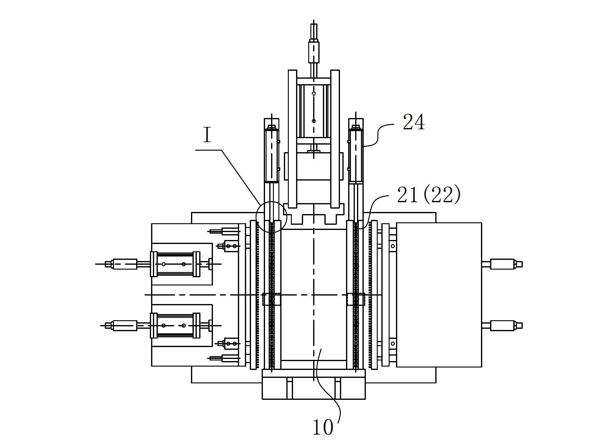
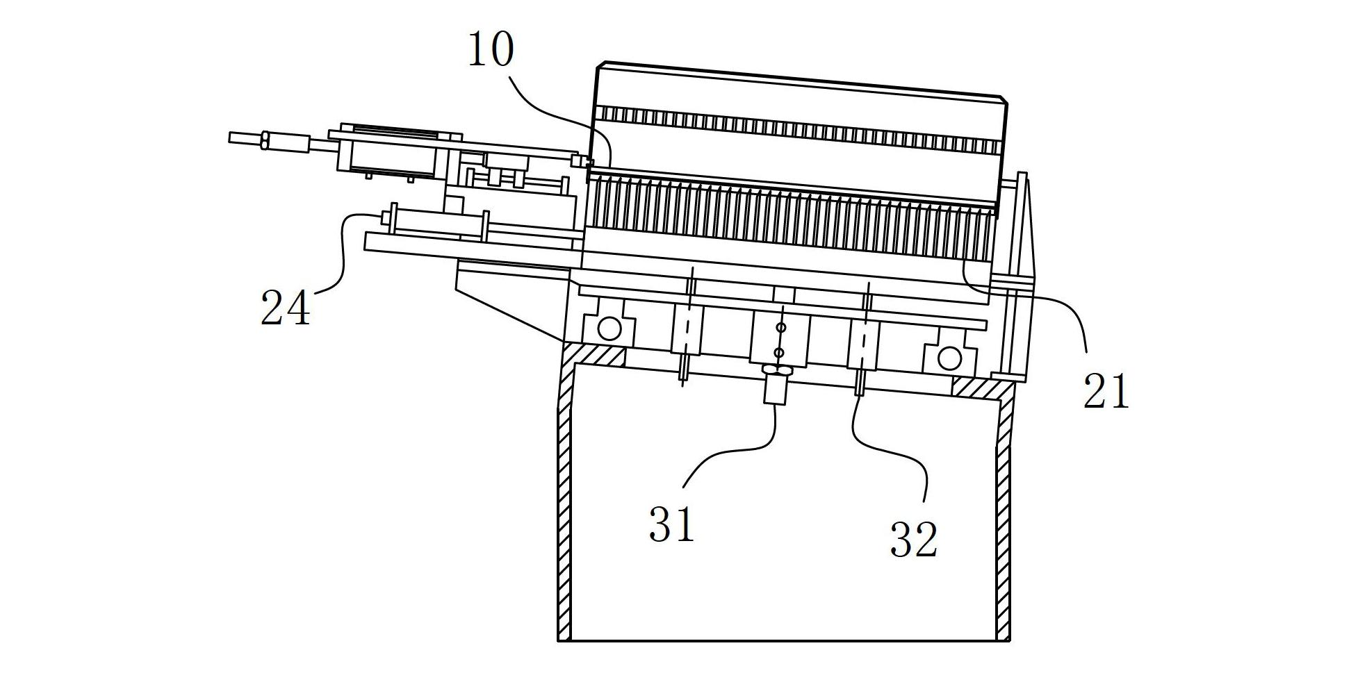
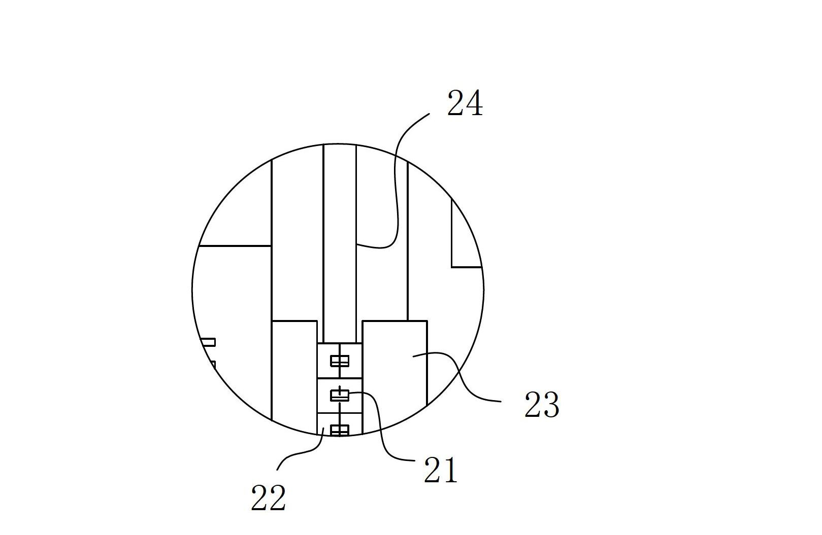
[0013] A positioning mechanism based on heat dissipation pipes, including a worktable 10 and a clamping unit for positioning and fixing the heat dissipation pipes arranged at least on one side of the worktable, the clamping unit includes a plurality of guide strips 21 arranged in parallel with each other The gap between the guide strips 21 constitutes the clamping interface on the clamping unit for positioning and fixing the heat dissipation pipe so that the plate surface is in an inclined or vertical direction. The arrangement direction of the guide strips 21 is set parallel to or intersects with the arrangement direction of the heat dissipation pipes, and the guide strips 21 have two position states of close together and outward expansion along the arrangement direction; when each guide strip 21 on the clamping unit is in the In the expanded state along its arrangement direction, the minimum distance between the card interfaces is greater than the bandwidth of the heat dissip...


PUM


Abstract

The invention belongs to the field of heat radiator assembly and particularly relates to a positioning mechanism based on heat radiating tubes. The positioning mechanism comprises a work table surface and a clamp connection unit, wherein the clamp connection unit comprises a plurality of guide strips in mutually parallel arrangement, gaps among the guide strips form a clamp connection opening arranged on the clamp connection unit, the guide strips are in arrangement in a mode that the arrangement direction of the guide strips is parallel to or intersected with the arrangement direction of the heat radiating tubes. When each guide strip arranged on the clamp connection unit is respectively in an external expansion state in the arrangement direction of the guide strips, the minimum gap of the clamp connection opening is greater than the heat radiating strip width in the flat straight state. When each guide strip arranged on the clamp connection unit is respectively in the gathering state, the minimum gap of the clamp connection opening is equal to the heat radiating strip width in the flat straight state. The positioning mechanism also comprises a motive power unit, when the motive power unit is positioned in an initial position, the clamp connection unit is positioned at a work platform part, and after the gathering action of the clamp connection unit is completed, the motive power unit acts and drives the clamp connection unit to move away from the work platform. The positioning mechanism has the advantages that the assembly positioning force is balanced, and the work efficiency is high.

Description

technical field [0001] The invention belongs to the field of radiator assembly, and in particular relates to a positioning mechanism based on a heat dissipation pipe. Background technique [0002] Radiators are an integral part of a car's cooling system. The radiator in the engine water cooling system is usually in the shape of a square frame, consisting of a water inlet chamber, a water outlet chamber, a heat dissipation belt, and a flat tube-shaped heat dissipation pipe. When assembled, the heat dissipation belt and the heat dissipation pipe are arranged alternately one by one. , relying on the splints arranged on both sides to achieve sequential fixation relative to the heat dissipation belt and the two ends of the heat dissipation pipe, and relying on the fixing plates arranged at both ends to realize the clamping and fixing of the heat dissipation belt and the two ends of the heat dissipation pipe, and the outer side of the fixing plate is set with plastic The layer an...

Claims


Application Information

Patent Timeline
Patent Type & Authority Applications(China)
IPC IPC(8): B23P21/00B25H1/10
Inventor 方兴武
Owner HUANGSHAN KENENG AUTO RADIATOR
Why Eureka
Try Eureka