
Binding tape cutting machine capable of achieving automatic feeding and discharging

A technology of automatic loading and unloading and strip cutting machine, which is applied in metal processing and other directions, and can solve the problems of adjustment, automatic loading and unloading, automatic centering and clamping, and cutting width.

Inactive Publication Date: 2022-01-25
YANCHENG INST OF TECH
View PDF0 Cites 1 Cited by
  • Summary
  • Abstract
  • Description
  • Claims
  • Application Information

AI Technical Summary

Problems solved by technology

[0004] The present invention provides a cutting and binding machine capable of automatic loading and unloading, aiming to solve the above-mentioned problems in the prior art that cannot be automatically loaded and unloaded, cannot be automatically centered and clamped, and cannot adjust the cutting width

Method used

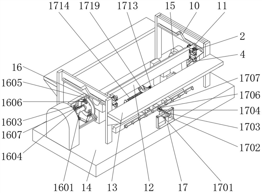
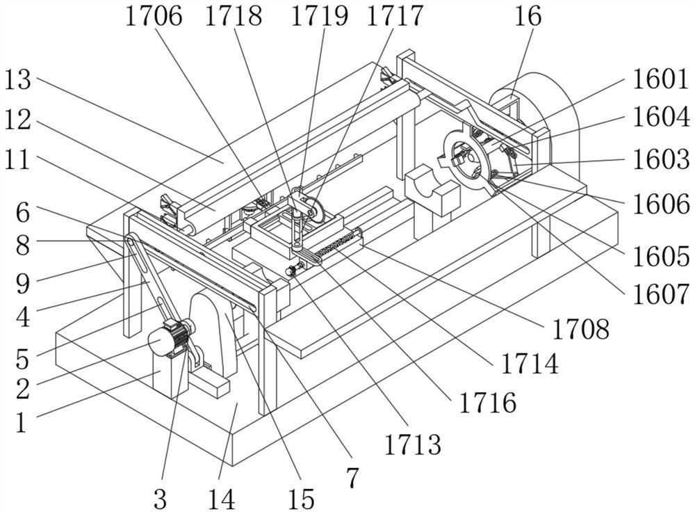
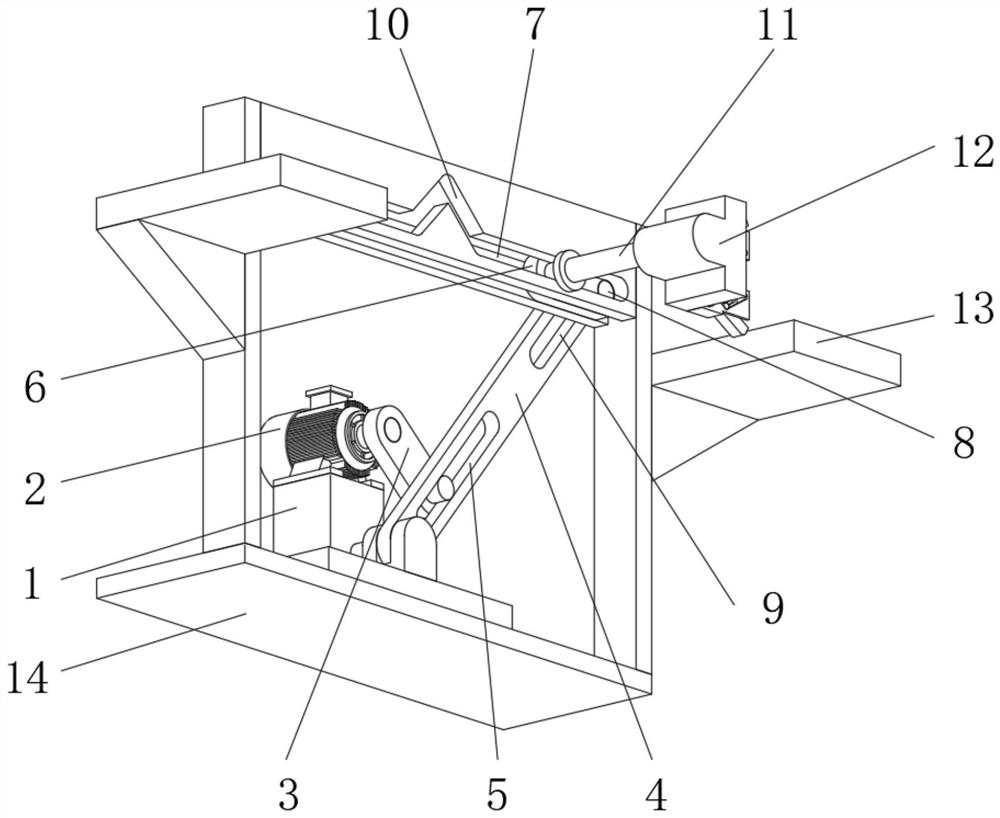

Image

  • Binding tape cutting machine capable of achieving automatic feeding and discharging
  • Binding tape cutting machine capable of achieving automatic feeding and discharging
  • Binding tape cutting machine capable of achieving automatic feeding and discharging

Examples


Embodiment Construction

[0030] In order to make the purpose, technical solutions and advantages of the embodiments of the present invention clearer, the technical solutions in the embodiments of the present invention will be clearly and completely described below in conjunction with the drawings in the embodiments of the present invention. Obviously, the described embodiments It is a part of embodiments of the present invention, but not all embodiments. The components of the embodiments of the invention generally described and illustrated in the figures herein may be arranged and designed in a variety of different configurations.

[0031]Accordingly, the following detailed description of the embodiments of the invention provided in the accompanying drawings is not intended to limit the scope of the claimed invention, but merely represents selected embodiments of the invention. Based on the embodiments of the present invention, all other embodiments obtained by persons of ordinary skill in the art wit...


PUM


Abstract

The invention provides a binding tape cutting machine capable of achieving automatic feeding and discharging, and belongs to the technical field of binding tape cutting machines. The binding tape cutting machine comprises a feeding frame, a swing hole plate, an overturning plate, a horizontal limiting groove and an overturning hole groove, wherein the top end of the feeding frame is fixedly connected with a feeding motor, a rotary plate used for driving the swing hole plate to vertically swing is installed at the output end of the feeding motor, and a driving hole groove is formed in the connecting portion of the rotary plate and the swing hole plate. When the binding tape cutting machine is used, a horizontal limiting groove and an overturning hole groove are arranged, in the feeding frame, the rotary plate rotates to drive the swing hole plate to swing through the driving hole groove, the swing hole plate swings to drive a driving guide column to horizontally slide along the horizontal limiting groove through the driven hole groove, so that the driving guide column moves to drive the driven guide column to slide along an inverted-V-shaped overturning hole groove through the overturning plate, the driven guide column drives the overturning plate to overturn, and automatic feeding and discharging operation of raw materials is achieved.

Description

technical field [0001] The invention relates to the field of building plate processing, in particular to a cutting and binding machine capable of automatic loading and unloading. Background technique [0002] The strip cutting machine is suitable for cutting strips, cutting (rolling) The necessary choice for strips, suitable for umbrellas, foam, leather, reflective materials, nylon, chiffon, denim, mesh, plastic, Oxford cloth, non-woven fabrics, double-sided adhesive tape, acetate cloth and other materials in various widths and straight Strips, 45-degree oblique strips and horizontal strips are cut, cut, and bundled. [0003] The current cutting and binding machine has the problem of being unable to automatically load and unload materials when it is used in the production of plates, resulting in low work efficiency, and the problem that the cutting and binding machine cannot be automatically centered and clamped during use, resulting in the cutting and binding machine being...

Claims


Application Information

Patent Timeline
Patent Type & Authority Applications(China)
IPC IPC(8): B26D1/60B26D7/06B26D7/02B26D5/08B26D7/32
CPCB26D1/60B26D7/06B26D7/02B26D5/08B26D7/32
Inventor 王路明邱龙杜建周韩申杰钟栋青李延波
Owner YANCHENG INST OF TECH
Learn More