
Soft iron-brass composite band structure and welding method thereof

A technology of composite elastic belt and welding method, applied in welding equipment, warheads, ammunition and other directions, can solve the problems of restricting the belt, affecting the life of the gun body, and the rifling of the soft iron belt. Improve performance and functionality, increase the effect of charge

Inactive Publication Date: 2012-08-15
HARBIN INST OF TECH
View PDF7 Cites 12 Cited by
  • Summary
  • Abstract
  • Description
  • Claims
  • Application Information

AI Technical Summary

Problems solved by technology

However, the soft iron belt also has its disadvantages, mainly because the hardness of soft iron is higher than that of copper. When firing shells, the friction between the belt and the rifling, the wear of the soft iron belt on the rifling is more serious
The belts of the above two materials have their own advantages and disadvantages. Their shortcomings limit the function of the belt, and also affect the life of the gun body and the range of the shell.

Method used


Image

  • Soft iron-brass composite band structure and welding method thereof
  • Soft iron-brass composite band structure and welding method thereof
  • Soft iron-brass composite band structure and welding method thereof

Examples


Embodiment 1

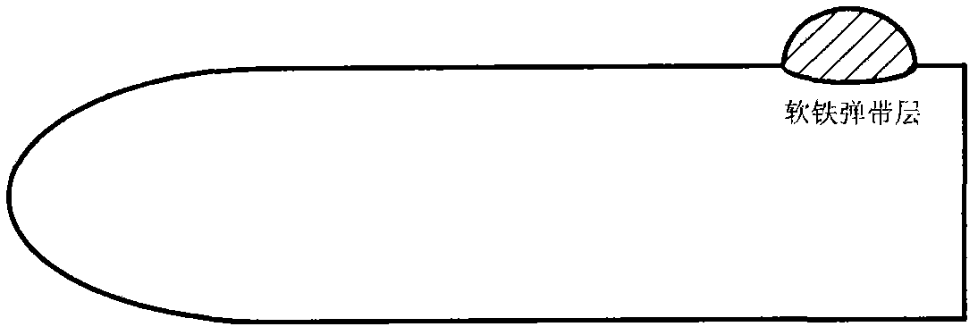
[0017] Example 1: Combining figure 1 , a soft iron-brass composite elastic belt structure of the present invention, two kinds of material are used for overlay welding to form elastic belt on the surface of the elastic body, wherein the soft iron part is located at the rear part of the elastic belt, and the brass part is located at the front part of the elastic belt.

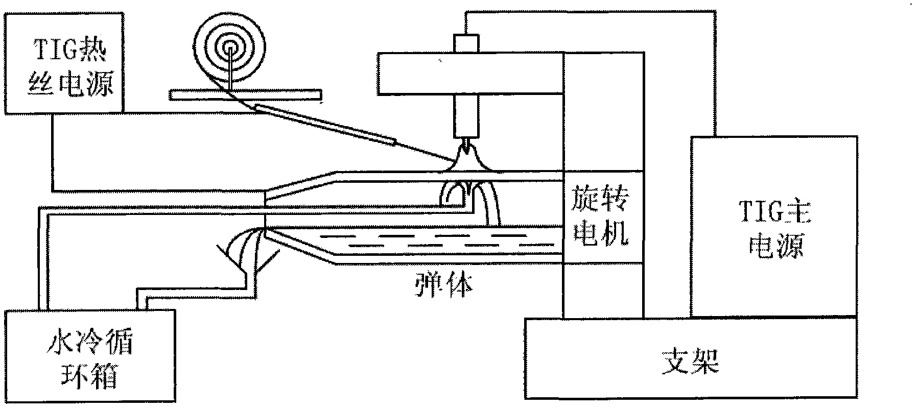
[0018]The invention relates to a welding method of a soft iron-brass composite elastic belt structure, which adopts tungsten argon arc welding, and arc hot wire semi-automatically feeds the elastic belt for welding, and connects the two electrodes of the auxiliary TIG power supply to the wire feeder respectively. On the nozzle and the workpiece, a conductive circuit is formed. When the welding process starts, the main welding circuit is connected, the main arc is ignited to preheat the workpiece for 1-2 seconds, and then the welding wire is fed through the wire feeding device. When the distance between the end of ...

Embodiment 2

[0019] Example 2: Combining figure 1 , figure 2 , image 3 , Figure 4 , Figure 5 , Figure 6 , a soft iron-brass composite elastic belt structure and its welding method according to the present invention, the main feature is that the elastic belt adopts a welding structure composed of two different materials, forming a composite elastic belt with soft iron behind and copper in front structure, such as figure 1 shown.

[0020] The welding belt structure proposed by the present invention is suitable for the belt manufacturing process of shells with a diameter of 30-100 mm. The welding method selected is hot wire TIG, that is, tungsten argon arc welding and arc hot wire semi-automatic feeding. Welding of elastic belts, such as figure 2 shown. Connect the two electrodes of the secondary TIG power supply to the wire feed nozzle and the workpiece respectively to form a conductive loop. At the beginning of the welding process, connect the main welding circuit, ignite the...


PUM

PropertyMeasurementUnit
thicknessaaaaaaaaaa
diameteraaaaaaaaaa
shear strengthaaaaaaaaaa

Abstract

The invention provides a soft iron-brass composite band structure and a welding method thereof. The soft iron-brass composite band structure uses two materials of soft iron and brass to overlay on the surface of an elastic body; the soft iron is located at the back of a band; and a brass part is located at the front part of the band. The welding method comprises the following steps of: firstly, welding a soft iron part; overlaying the brass part after cutting and machining to be flat; and finally, secondarily machining to form the entire band meeting design requirements. According to the soft iron-brass composite band structure and the welding method thereof provided by the invention, the properties and functions of the band can be improved by using own characteristics of the brass and the soft iron to complement the advantages of the brass and the soft iron. The characteristic of good air closeness of a soft iron band is maintained by using the composite band, so as to achieve a wider cannonball firing range. Compared with a brass band, the composite band only has the advantage that a half amount of the brass is used, so that the manufacturing cost is lowered. The composite band has the advantage of larger flexibility. Compared with the brass band, the soft iron band has the advantages of high strength, high rigidity and better air closeness. The rigidity, air closeness and the like of the band can be adjusted by adjusting the ratio of the soft iron and the brass in the band.

Description

(1) Technical field [0001] The invention relates to welding technology, in particular to a soft iron-brass composite elastic belt structure and a welding method thereof. (2) Background technology [0002] Alloy structures deposited on the surface of steel substrates are widely used in the fields of aerospace and weapon manufacturing, such as the assembly of shell belts. The deep groove is not conducive to reducing the wall thickness and increasing the charge, so as to affect the blasting power. New types of projectiles such as terminal-sensitive projectiles, submunitions, prefabricated fragmentation projectiles, etc., if the old technology is still used, it will cause great difficulties to the overall structural design. This is one of the key bottleneck technologies for the manufacture of new projectiles. Research on new welding technologies will change The existing chimera technology has great practical value. The key technology to improve the combat effectiveness of arti...

Claims


Application Information

Patent Timeline
Patent Type & Authority Applications(China)
IPC IPC(8): F42B14/02B23K9/167B23K9/04
Inventor 吕世雄崔庆龙黄永宪敬小军磨安详郑传奇曲杰
Owner HARBIN INST OF TECH
Learn More