Condensing system for window-type air conditioners

A technology for condensing systems and air conditioners, applied in air conditioning systems, evaporators/condensers, refrigerators, etc., can solve the problems of low heat exchange efficiency of condensers, and achieve the effect of improving heat exchange efficiency

Inactive Publication Date: 2012-08-15
HAIER GRP CORP +1
View PDF10 Cites 5 Cited by
  • Summary
  • Abstract
  • Description
  • Claims
  • Application Information

AI Technical Summary

Problems solved by technology

The technical defect of the above-mentioned published patent is that the heat exchange efficiency of the condenser is low

Method used


Image

  • Condensing system for window-type air conditioners
  • Condensing system for window-type air conditioners
  • Condensing system for window-type air conditioners

Examples


Embodiment Construction

[0024] Specific embodiments of the present invention will be described below with reference to the accompanying drawings.

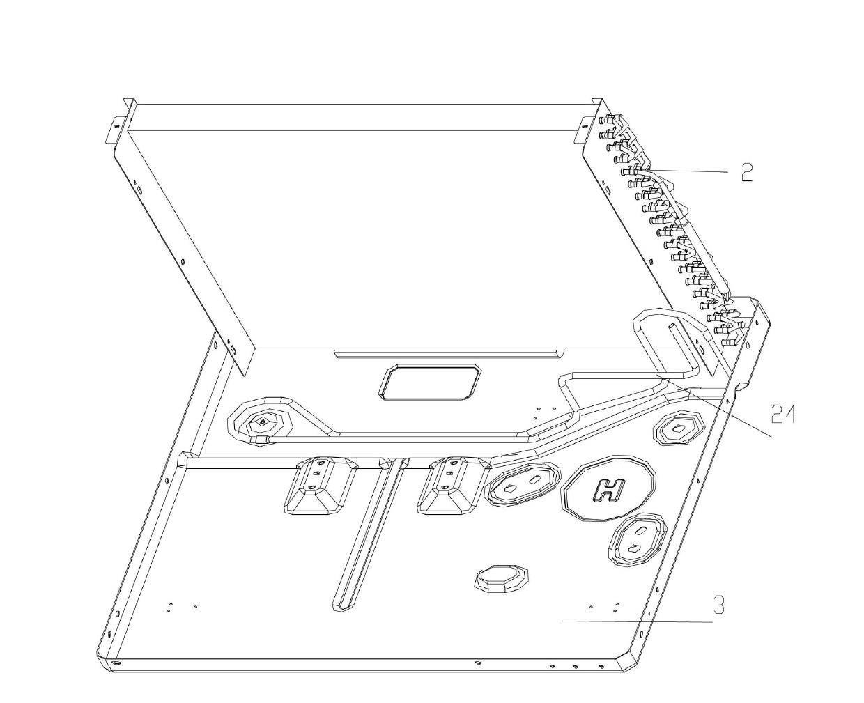
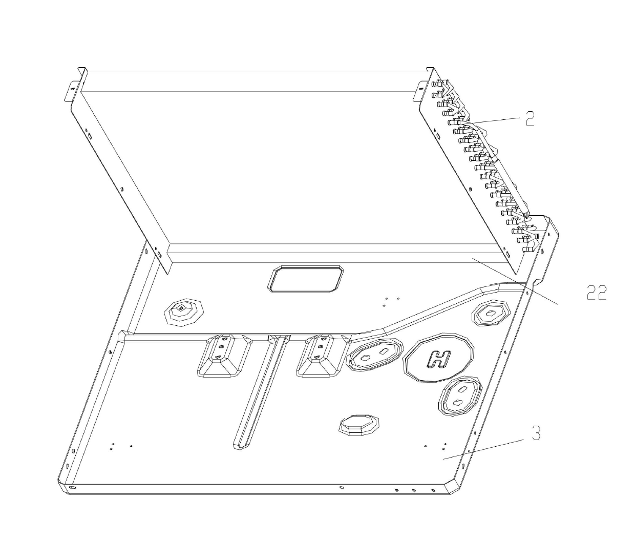
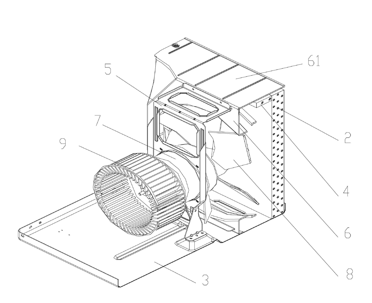
[0025] see Figure 3-5 , the condensing system of the window air conditioner of the present invention comprises: axial flow fan 8, condenser 2, cooler 4, compressor 13, wherein the exhaust port of compressor 13, the inlet end of cooler 4, the outlet of cooler 4 end, and the refrigerant inlet of the condenser 2 are sequentially connected to form a refrigerant passage.

[0026] The cooler has a cooling coil, and the inlet and outlet of the cooling coil constitute the inlet and outlet ports of the cooler respectively, so that the cooler 4 can be blown by the axial fan 8 and the condensed water thrown off by the axial fan 8 Cooling together, the position of the cooler 4 is set to: be fixed on the side of the top plate 61 facing the axial flow fan 8 in the rear partition, and be located above the axial flow fan 8, and on the inside of the condenser 2 (the win...


PUM


Abstract

The invention provides a condensing system for window-type air conditioners, which comprises a compressor (13), an axial fan (8), a condenser (2) and a cooler (4), wherein the condenser (2) is dead against the axial air outlet side of the axial fan (8), the cooler (4) is provided with a cooling coil, an inlet and an outlet of the cooling coil are respectively formed into an inlet end and an outlet end of the cooler, the cooler (4) is arranged in an air blowing path between the axial fan (8) and the condenser (2) and is positioned in the position collided with the condensed water circumferentially thrown out of the axial fan, and an air outlet of the compressor (13), the inlet end of the cooler (4), the outlet end of the cooler (4) and a refrigerant inlet of the condenser (2) are sequentially communicated so as to form a refrigerant path. According to the invention, a super-cooling section of the condenser in a window-type air conditioner can be effectively increased, thus the heat exchange efficiency of the condenser is improved.

Description

technical field [0001] The invention relates to a condensing system of a window type air conditioner. Background technique [0002] Generally speaking, in order to meet the heat transfer requirements, the condenser split design of the window unit (window air conditioner, referred to as the window unit) will be roughly divided into three parts, which can be called the superheating section, the mixing section, and the subcooling section. . Among them, in the superheating section, the refrigerant has just been discharged from the compressor and is in a high-temperature gas state. In the subcooling section, the refrigerant exists in the condenser in liquid form after passing through the condenser for heat dissipation, and due to the throttling of the subcooling tube and other throttling devices. Appropriately increasing the subcooling section of the condenser and reducing the superheating section can improve the heat exchange efficiency of the condenser. [0003] In the desig...

Claims


Application Information

Patent Timeline
IPC IPC(8): F24F1/02F24F13/30F25B39/04F24F1/0323F24F1/0284
CPCF24F13/30F24F13/224F24F1/0323F24F1/0284
Inventor 王友宁曾福祥张鹏王若峰王彦生
Owner HAIER GRP CORP
Why Eureka
Try Eureka