
Collected waste heat recycling oven

An oven and waste heat technology, applied in the direction of pretreatment surface, coating, surface coating liquid device, etc., can solve the problems of more energy consumption, safety hazards, complex structure, etc., to reduce the heating tube power and avoid safety Hidden dangers and the effect of avoiding energy loss

Active Publication Date: 2014-02-12
SHENZHEN HAONENG TECH
View PDF3 Cites 0 Cited by
  • Summary
  • Abstract
  • Description
  • Claims
  • Application Information

AI Technical Summary

Problems solved by technology

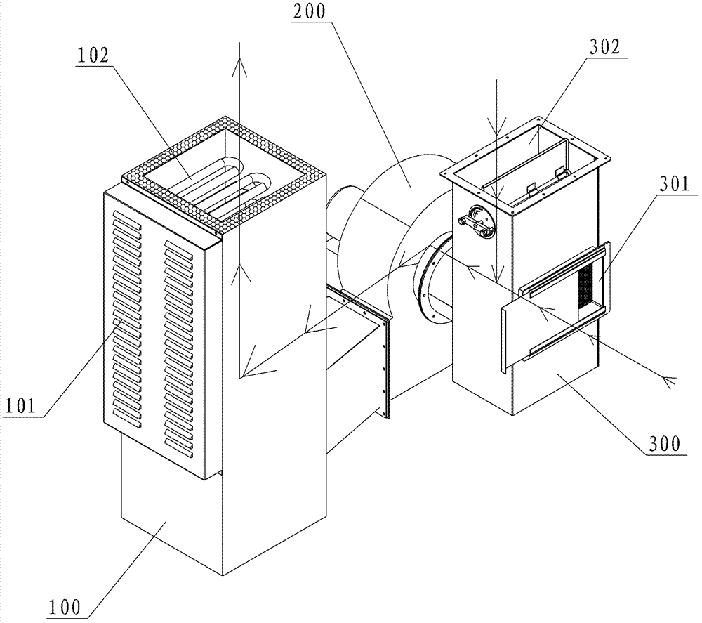
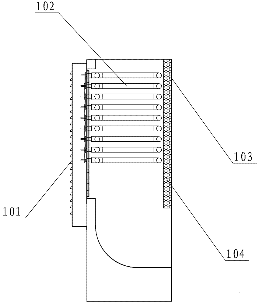
Thus the circulating air in the oven and the fresh air inlet 301 (usually cold air, about 20 degrees), after mixing, enter the first box body 100 under the drive of the blower 200, and transport it back to the oven after being heated by its heating pipe 102, so Although the wind path is simple, the structure of the first box body 100 is relatively complicated, and the louver heat dissipation cover 101 needs to be provided for the heating pipe 102. At the same time, it needs to be filled with thermal insulation cotton in consideration of heat preservation. Not only the structure is complicated, but also the end of the heating pipe 102 The heat is not utilized, and more energy is needed to heat the fresh air at room temperature. Moreover, the temperature of the outer tank of the first box body 100 is also high during work. Once people touch it, they will be burned, and there are certain safety hazards. Therefore, there are room for further improvement

Method used


Image

  • Collected waste heat recycling oven
  • Collected waste heat recycling oven
  • Collected waste heat recycling oven

Examples


Embodiment Construction

[0018] In order to describe the technical content, structural features, achieved goals and effects of the present invention in detail, the following will be described in detail in conjunction with the embodiments and accompanying drawings.

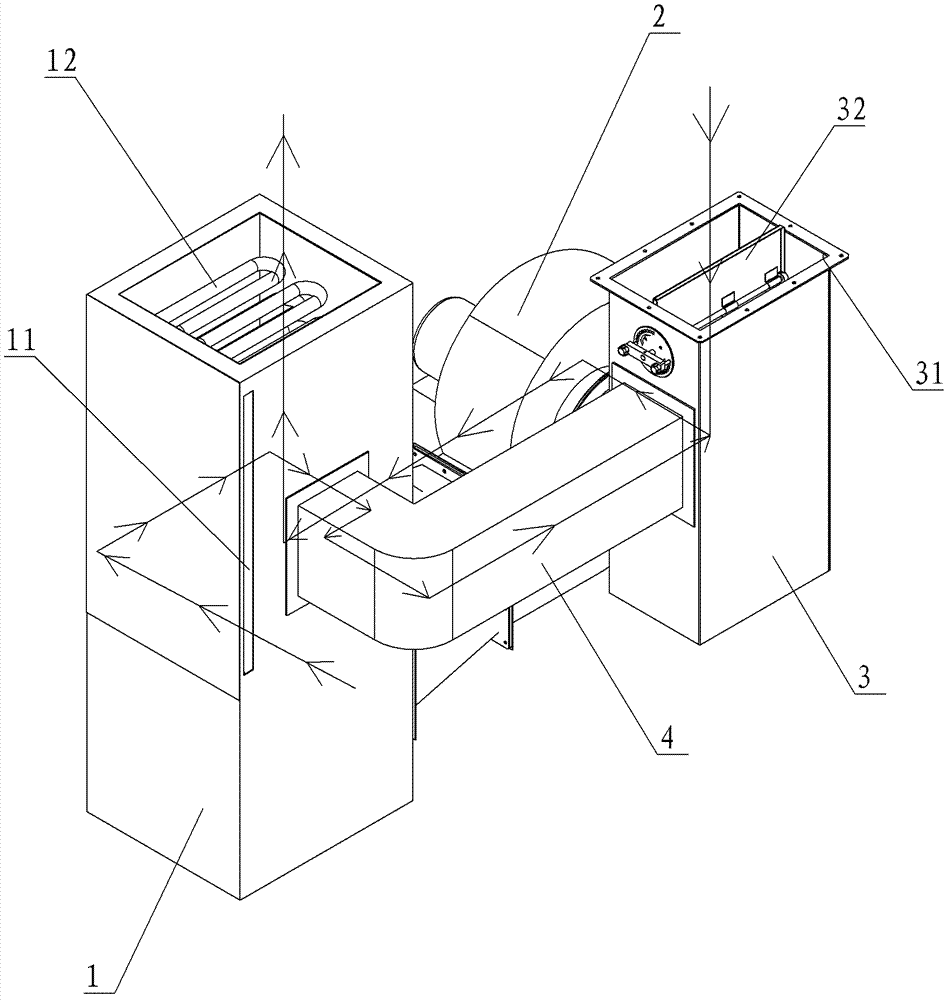
[0019] see image 3 as well as Figure 4 , The present invention relates to a recycling oven for waste heat collection, which includes a first box 1, a blower 2, a second box 3, a heating pipe 12 and a preheating air communication pipe 4.

[0020] Wherein, the first box body 1 includes an inner container 13 and an outer container 14 . The inner bag 13 is hollow to form a first fluid channel 17, and a second fluid channel 15 is formed between the inner bag 13 and the outer bag 14. Considering the characteristics of the fluid, preferably, the second fluid channel 15 is formed by the inner bag. 13. The side walls of the outer bladder 14 are formed by airtight intervals. In addition, the inner tank 13 is also provided with a fluid inlet 18 ...


PUM


Abstract

The invention provides a collected waste heat recycling oven which comprises a first oven body, a blast blower, a second oven body, a heating pipe and a preheated wind communicating pipe. An inner chamber and an outer chamber of the first oven body are additionally provided with a fresh wind circulating wind path, thus the inner chamber and the outer chamber of the first oven body do not need to be filled with heat preservation cotton, and meanwhile a shutter heat dissipating hood is not in need; after fresh wind enters the wind path, can absorb the heat of the end of the heating pipe so as to take away heat produced by the end of the heating pipe; therefore, the heat dissipation problem is solved, the burning problem caused by the overheated end of the heating pipe is avoided; a purpose of collecting and recycling waste heat is achieved; the unnecessary energy consumption loss of the original structure is avoided; and the temperature of the outer chamber can be lowered so as to effectively avoid potential safety hazard of scalding. The experiment shows that the collected waste heat recycling oven has the following beneficial effects: the room-temperature fresh wind which is about 20DEG C can reach 50DEG C after passing through a preheating wind path, and the fresh wind and the circulating wind of the second oven body are mixed and enters the first oven body to be heated, so as to effectively reduce the power of the heating pipe and save the energy.

Description

technical field [0001] The invention relates to an industrial drying device, in particular to an oven for collecting waste heat and recycling. Background technique [0002] The coating process is widely used in new energy batteries, solar cells, optical films, flexible circuit boards and other industries, and it is also a key process that directly affects product quality. Coating is the process of uniformly, continuously or discontinuously coating the prepared paste-like viscous slurry on the front and back sides of the substrate (aluminum foil or copper foil), and then drying. Therefore, drying is particularly important for the coating process. The drying effect directly affects the accuracy of the coated product, and the drying efficiency also directly affects the production efficiency of the equipment. [0003] When it comes to the drying process, the dryer is an indispensable equipment, and the ovens of the existing dryers are all equipped with certain energy-saving des...

Claims


Application Information

Patent Timeline
Patent Type & Authority Patents(China)
IPC IPC(8): B05D3/02B05D3/04
Inventor 苏建贵
Owner SHENZHEN HAONENG TECH
Learn More