Capacitance deterioration detection device for resistance-capacitance device of railway signals equipment

A railway signal and deterioration detection technology, applied in measuring devices, measuring resistance/reactance/impedance, instruments, etc., can solve the problems that affect the normal use of signal equipment, reduce relay delay time, and equipment cannot work normally, etc. The effect of uninterrupted and continuous operation, reducing workload and improving railway transportation efficiency

Active Publication Date: 2012-08-08
LIUZHOU CHENTIAN TECH
View PDF6 Cites 12 Cited by
  • Summary
  • Abstract
  • Description
  • Claims
  • Application Information

AI Technical Summary

Problems solved by technology

When the capacitance decreases, the delay time of the relay will become smaller, causing the equipment to not work normally, affecting the normal use of the signal equipment and reducing the driving efficiency
At present, it is impossible to conduct qualitative or quantitative online detection of the capacity change of the capacitance of the resistance capacitor device widely used in railway signal equipment. In order to ensure the normal operation of the signal equipment, only manual detection or regular replacement can be adopted.
Manual inspection has a large workload and low efficiency. On the one hand, regular replacement will cause unnecessary waste, and on the other hand, it will also leave potential safety hazards

Method used


Image

  • Capacitance deterioration detection device for resistance-capacitance device of railway signals equipment
  • Capacitance deterioration detection device for resistance-capacitance device of railway signals equipment
  • Capacitance deterioration detection device for resistance-capacitance device of railway signals equipment

Examples


Embodiment 1

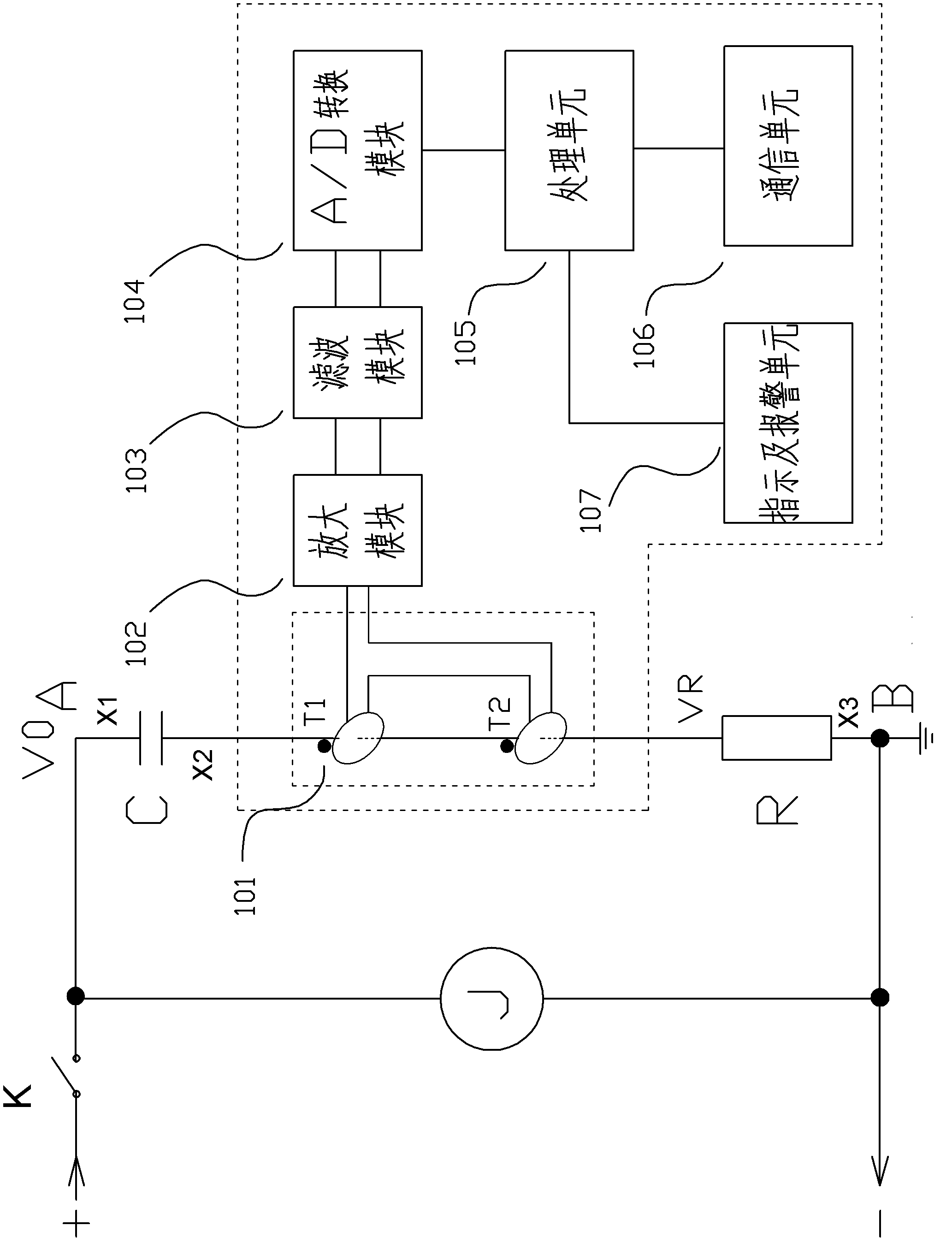
[0032] A capacitance degradation detection device for a resistance capacitance device of railway signal equipment, characterized in that the detection device includes a current sampling module 101, an amplification module 102, a filtering module 103, an A / D conversion module 104, a processing unit 105, and a communication unit 106 And indication and alarm unit 107, the primary end of the current sampling module is serially connected to the X2 section between the A end and the B end of the detected resistance capacitor device, the output end is connected to the amplification module 102, the amplification module 102, the filter module 103, A / The D conversion module 104 and the processing unit 105 are sequentially connected (that is, the amplification module 102 is connected to the filter module 103, the filter module 103 is connected to the A / D conversion module 104, and the A / D conversion module 104 is connected to the processing unit 105), the communication unit 106 and The in...

Embodiment 2

[0045] A capacitance degradation detection device for a resistance capacitance device of railway signal equipment, the basic structure of which is the same as that of Embodiment 1, including a current sampling module 101, an amplification module 102, a filtering module 103, an A / D conversion module 104, a processing unit 105, and a communication unit 106 and indication and alarm unit 107, the primary end of the current sampling module is serially connected to the X2 section between the A terminal and the B terminal of the detected resistance capacitor device, the output terminal of the current sampling module is connected to the amplification module 102, the amplification module 102, the filtering The module 103, the A / D conversion module 104, and the processing unit 105 are connected sequentially (that is, the amplification module 102 is connected with the filter module 103, the filter module 103 is connected with the A / D conversion module 104, and the A / D conversion module 104...

Embodiment 3

[0059] A capacitance degradation detection device for a resistance capacitance device of railway signal equipment, the basic structure of which is the same as that of Embodiment 1, including a current sampling module 101, an amplification module 102, a filtering module 103, an A / D conversion module 104, a processing unit 105, and a communication unit 106 and indication and alarm unit 107, the primary end of the current sampling module is serially connected to the X2 section between the A terminal and the B terminal of the detected resistance capacitor device, the output terminal of the current sampling module is connected to the amplification module 102, the amplification module 102, the filtering The module 103, the A / D conversion module 104, and the processing unit 105 are connected sequentially (that is, the amplification module 102 is connected with the filter module 103, the filter module 103 is connected with the A / D conversion module 104, and the A / D conversion module 104...


PUM


Abstract

The invention provides a capacitance deterioration detection device for a resistance-capacitance device of railway signals equipment. The detection device comprises a current sampling module, an amplification module, a filtering module, an A / D (Analog / Digital) conversion module, a processing unit, a communication unit and an indication and alarm unit, wherein a primary side of the current sampling module is serially connected at any section between the end A and end B of a detected resistance-capacitance device, and the output end of the current sampling module is connected with the amplification module; and the amplification module, the filtering module, the A / D conversion module, the processing unit, the communication unit and the indication and alarm unit are sequentially connected. The device provided by the invention is simple in circuit structure and scientific in design, can be used for performing real-time and on-line isolated detection on the capacitance capacity of the detected resistance-capacitance device and realizing the on-line measurement and status display of the capacitance, is timely and accurate in detection, high in efficiency, high in accuracy, strong in interference resistance, safe and reliable, can ensure the uninterrupted continuous operation of the equipment, is favorable for improving the railway transportation efficiency, and also can be used for greatly reducing the workload of manual detection, reducing the labor intensity of detection technicists and saving the cost.

Description

technical field [0001] The invention relates to a state detection device for a resistance capacitor used in railway signal equipment, in particular to a capacitance degradation detection device for a resistance capacitor of railway signal equipment. Background technique [0002] Railway signaling equipment uses resistive capacitors to delay the pull-up or release time of relays (see appendix Figure 4 ) to meet the usage requirements. When the capacitance decreases, the delay time of the relay will become smaller, causing the equipment to not work normally, affecting the normal use of the signal equipment and reducing the driving efficiency. At present, it is impossible to conduct qualitative or quantitative on-line detection of the capacity change of the resistance capacitor device used in a large number of railway signal equipment. In order to ensure the normal operation of the signal equipment, only manual detection or regular replacement can be adopted. Manual inspectio...

Claims


Application Information

Patent Timeline
Patent Type & Authority Applications(China)
IPC IPC(8): G01R31/00G01R27/26
Inventor 李昱珺
Owner LIUZHOU CHENTIAN TECH
Why Eureka
Try Eureka