Speed change control device of automatic transmission

一种自动变速器、控制装置的技术,应用在传动装置控制、带有齿的元件、皮带/链条/齿轮等方向,能够解决变速冲击、联接压超出等问题,达到避免变速冲击的效果

Active Publication Date: 2012-08-08
JATCO LTD
View PDF7 Cites 9 Cited by
  • Summary
  • Abstract
  • Description
  • Claims
  • Application Information

AI Technical Summary

Problems solved by technology

[0004] However, in the case of shifting (before the end of the shift) and the engagement pressure of the release-side coupling element is sufficiently lowered, if the engagement pressure of the release-side coupling element increases as the accelerator pedal is depressed, the engagement pressure may exceed Specified amount, produces shifting shock

Method used


Image

  • Speed change control device of automatic transmission
  • Speed change control device of automatic transmission
  • Speed change control device of automatic transmission

Examples


Embodiment 1

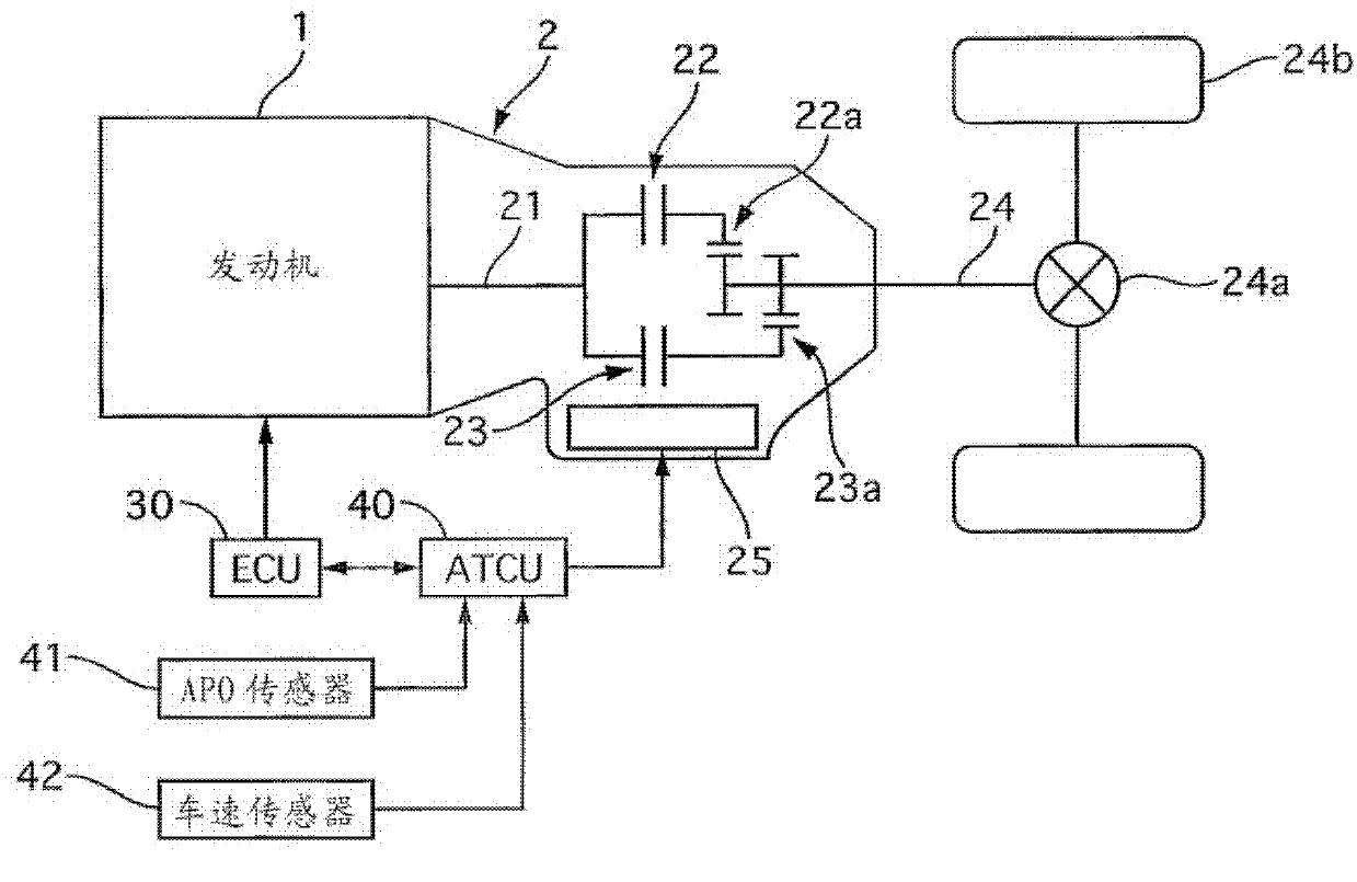
[0029] figure 1 It is a system diagram of a vehicle equipped with the shift control device of the automatic transmission according to the first embodiment. Such as figure 1 As shown, the engine 1 and the automatic transmission 2 are controlled by an electronic engine control unit (hereinafter referred to as ECU) 30 and an electronic control unit for transmission (hereinafter referred to as ATCU) 40 . The ECU 30 controls the engine 1 based on a throttle opening set by an APO sensor 41 that detects an accelerator opening and a vehicle speed input from a vehicle speed sensor 42 . Specifically, fuel injectors and ignition devices (not shown) are controlled in accordance with the running state.

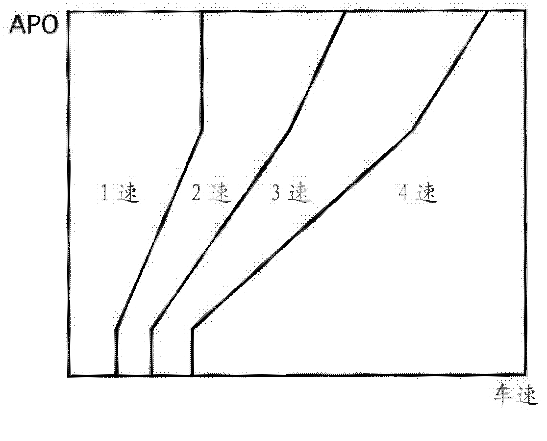
[0030] The ATCU 40 inputs the throttle opening degree input from the APO sensor 41 , the vehicle speed input from the vehicle speed sensor 42 , and the position of the shift lever detected by a disconnect switch not shown in the figure. Furthermore, based on the preset shift map (refer ...

Embodiment 2

[0061] Next, Example 2 will be described. Since the basic configuration is the same as that of Embodiment 1, only the points of difference will be described. Figure 7 It is a flowchart showing the downshift control process of the second embodiment. In Embodiment 1, when the release-side engagement pressure is less than a predetermined value, the second release-side engagement pressure correction process that prohibits the increase correction is performed. In contrast, Embodiment 2 is different in that when the release-side engagement pressure is less than a predetermined value, the release-side engagement pressure correction process is prohibited, and the release-side engagement pressure is reduced in this state. In other words, cancel Figure 5 The processing of step S51.

[0062] Figure 8 It is a time chart showing the downshift control process of the second embodiment. basically with Image 6 The time chart is the same as that of , except that at time t5, the decrea...

Embodiment 3

[0064] Next, Example 3 will be described. Since the basic configuration is the same as that of Embodiment 1, only the points of difference will be described. Figure 9 It is a flowchart showing the downshift control process of the third embodiment. Although this control process is described as a process executed at the time of downshifting, it is also applicable to the time of upshifting, and is not particularly limited. In this control process, only the release-side coupling element 23 will be described, and the description about the engagement-side coupling element 22 is basically the same as that in Embodiment 1 except that it is performed in parallel with the control of the release-side coupling element 23 after a downshift request. , so the description is omitted.

[0065] In step S1, it is determined whether there is a downshift request. If there is a downshift request, the process proceeds to step S102. Otherwise, this control flow ends.

[0066] In step S102, switch...


PUM


Abstract

The invention provides a speed change control device of an automatic transmission, which suppresses or at least minimizes the undesired shift shock even when, during speed change, an accelerator pedal is depressed. The automatic transmission changes a rotation speed inputted from a drive source into a preset speed change level in speed change levels and transmits the preset speed change level to a drive wheel. The speed change control device comprises a speed control section that, upon detecting a speed change instruction for a speed change from a speed-change before speed change level to a speed-change after speed change level, carries out the speed change by reducing an engaging pressure of a releasing side frictional element that has established the speed-change before speed change level and increasing an engaging pressure of an engaging side frictional element that would establish the speed-change after speed change level; a releasing side engaging pressure collection section that carries out a correction processing to increase the engaging pressure of the releasing side frictional element when a throttle open degree is increased during the speed change carried out by the speed control section; and an inhibition control section that inhibits the correction processing of the releasing side engaging pressure collection section when the engaging pressure of the releasing side frictional element is lower than a given value.

Description

technical field [0001] The invention relates to a shift control device of an automatic transmission. Background technique [0002] In the past, the speed change of the stepped automatic transmission was achieved by releasing the coupling element (hereinafter referred to as the coupling element on the release side) that realizes the shift stage before the shift, and coupling the coupling element (hereinafter referred to as the coupling element on the coupling side) that realizes the shift stage after the shift. And carried out. Patent Document 1 discloses a technique for suppressing fluctuations in the number of rotations of the turbine by increasing the engagement pressure of the release-side engagement element after the accelerator pedal is depressed during gear shifting. [0003] Patent Document 1: (Japanese) Patent No. 3097339 [0004] However, in the case of shifting (before the end of the shift) and the engagement pressure of the release-side coupling element is suffi...

Claims


Application Information

Patent Timeline
Patent Type & Authority Applications(China)
IPC IPC(8): F16H61/04F16H61/08
CPCF16H59/24F16H61/06F16H61/08F16H2306/42F16H61/04F16H61/061
Inventor 铃木正己山中史博
Owner JATCO LTD
Why Eureka
Try Eureka