
Control method for single-phase cascade type static synchronous compensator

A technology of static synchronous compensation and control method, applied in reactive power adjustment/elimination/compensation, output power conversion device, irreversible DC power input conversion into AC power output and other directions, can solve the problem of reaching the device withstand voltage level, Problems such as unbalanced DC side voltage and threats to the safe operation of the device, to achieve the effect of small overshoot

Active Publication Date: 2013-10-09
HUNAN UNIV
View PDF3 Cites 0 Cited by
  • Summary
  • Abstract
  • Description
  • Claims
  • Application Information

AI Technical Summary

Problems solved by technology

However, because the power device is not an ideal device, there are switching losses, and the static synchronous compensator needs to obtain a certain amount of active power from the grid to maintain the voltage stability of the DC side.
The DC side capacitors of each cascaded unit of the cascaded static synchronous compensator are independent of each other, and the dispersion of parameters, the difference in switching loss and the difference in pulse delay will cause the DC side voltage to be unbalanced
[0005] The unbalanced DC side voltage, on the one hand, will increase the harmonic content of the output current of the device; on the other hand, when the unbalanced phenomenon is particularly serious, it will cause the DC side voltage of some cascaded units to be too high, reaching the withstand voltage level of the device. Threat to the safe operation of the entire device

Method used


Image

  • Control method for single-phase cascade type static synchronous compensator
  • Control method for single-phase cascade type static synchronous compensator
  • Control method for single-phase cascade type static synchronous compensator

Examples


Embodiment Construction

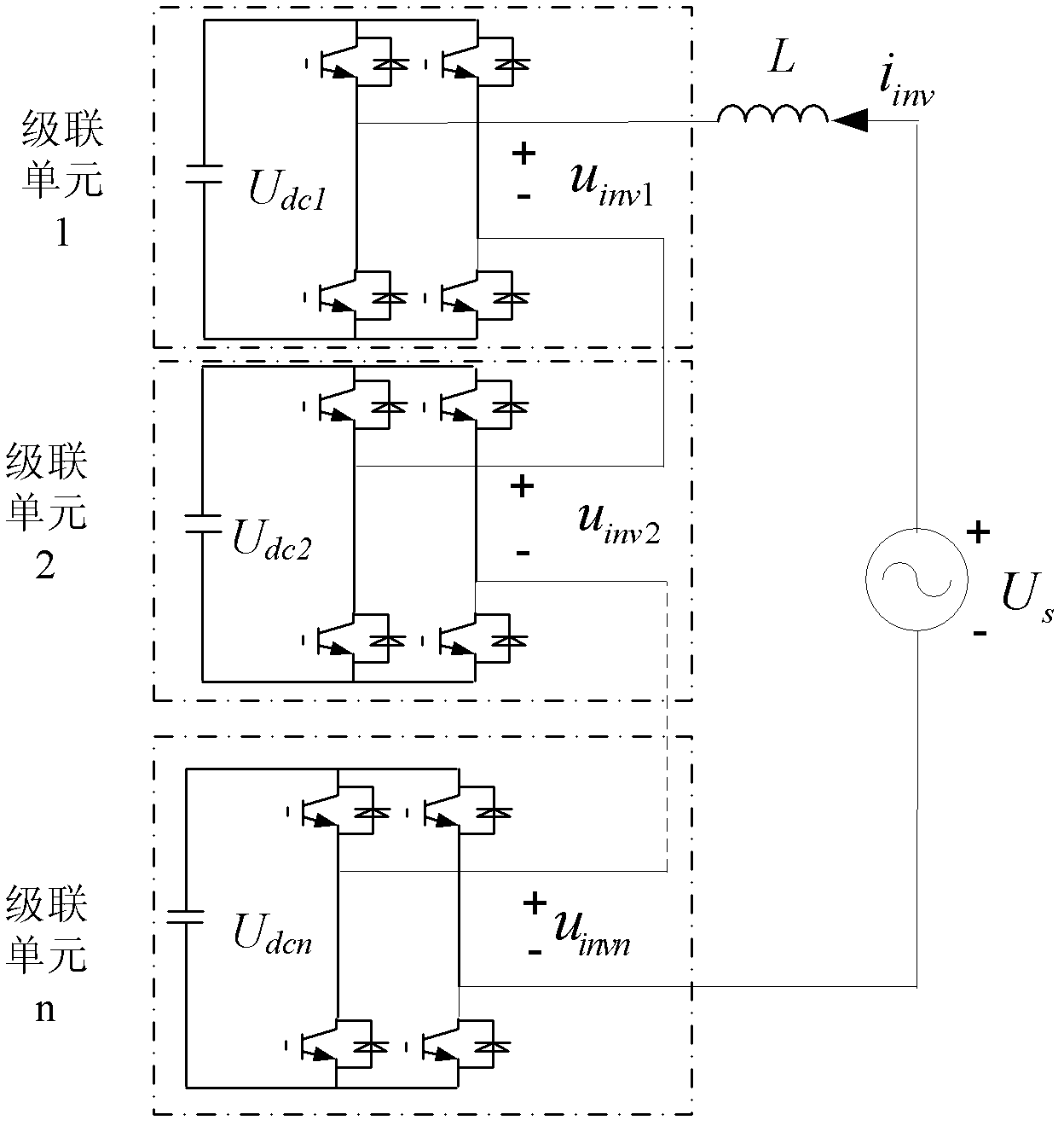
[0028] figure 1 It is the main circuit structure diagram of the single-phase cascaded static synchronous compensator. The single-phase full-bridge inverter circuit is used as the cascaded unit, and multiple cascaded units are directly connected in series at the output end, and then connected to the power grid through the connecting reactor L. . Its working principle is to make the compensator absorb or send out the reactive current that meets the requirements by properly adjusting the phase and amplitude of the output voltage of each cascaded unit, so as to realize the purpose of dynamic reactive power compensation. u inv1 , u inv2 … u invn is the output terminal voltage of each cascaded unit, U dc1 , U dc2 … U dcn is the DC side voltage of each cascaded unit, i inv is the instantaneous value of the output current of the compensator.

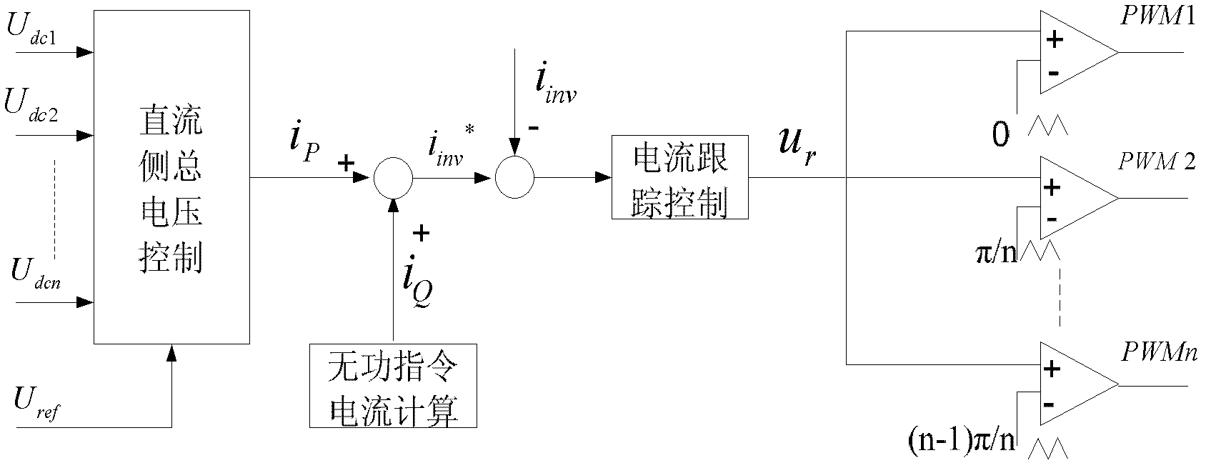
[0029] figure 2 It is a block diagram of double closed-loop control of single-phase cascaded static synchronous compensator. The vol...


PUM


Abstract

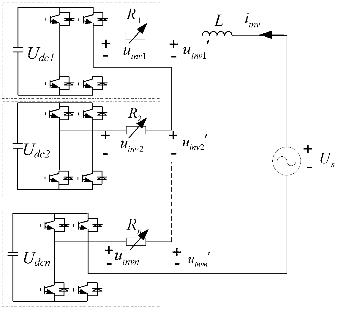
The invention discloses a control method for a single-phase cascade type static synchronous compensator, which comprises leading direct current side level balance control based on virtual resistance on the basis of double-closed-loop transient value control composed of a direct current side total voltage outer ring and a current tracing inner ring, and constructing the controllable virtual resistance at the output end of each cascade unit; comparing a practical value of direct current side voltage of each cascade unit with a set value, adjusting each virtual resistance according to a comparison result, independently adjusting input power of each cascade unit from a power grid to meet different requirements of each cascade unit for the input power due to different consumption and achieve the purpose of direct current side voltage balance control. The control method for the single-phase cascade type static synchronous compensator can achieve tracing control of output current of the compensator and balance of the direct current side voltage of each cascade unit under the condition that hardware circuits are not added.

Description

technical field [0001] The invention relates to a single-phase cascaded static synchronous compensator, in particular to a control method for the single-phase cascaded static synchronous compensator. Background technique [0002] Limited by the voltage level and power level of power devices, the main circuit structures suitable for medium and high voltage high-power static synchronous compensators (STATCOM) mainly include: three-phase bridge structure based on device series connection, clamping multi-level structure and cascade structure. [0003] Among them, the main circuit structure of the cascaded static synchronous compensator: the single-phase full-bridge inverter circuit is used as the cascaded unit, and multiple cascaded units are directly connected in series at the output end, and then connected to the power grid through a connecting reactor. Its working principle is to make the compensator absorb or send out the reactive current that meets the requirements by prop...

Claims


Application Information

Patent Timeline
Patent Type & Authority Patents(China)
IPC IPC(8): H02J3/18H02M7/49
CPCY02E40/16H02J3/1857Y02E40/10Y02E40/20H02M7/4835
Inventor 罗安熊桥坡刘芸寇磊周发云黎小聪刘雷马伏军
Owner HUNAN UNIV
Learn More