Synchronous control system of step scanning photoetching machine based on VME (Virtual Mobile Engine) bus and synchronous control method thereof
A technology of synchronous control and step-scanning, applied in the directions of comprehensive factory control, electrical program control, and comprehensive factory control, which can solve the problems of low lithography efficiency and large synchronization error.
- Summary
- Abstract
- Description
- Claims
- Application Information
AI Technical Summary
Problems solved by technology
Method used
Image
Examples
specific Embodiment approach 1
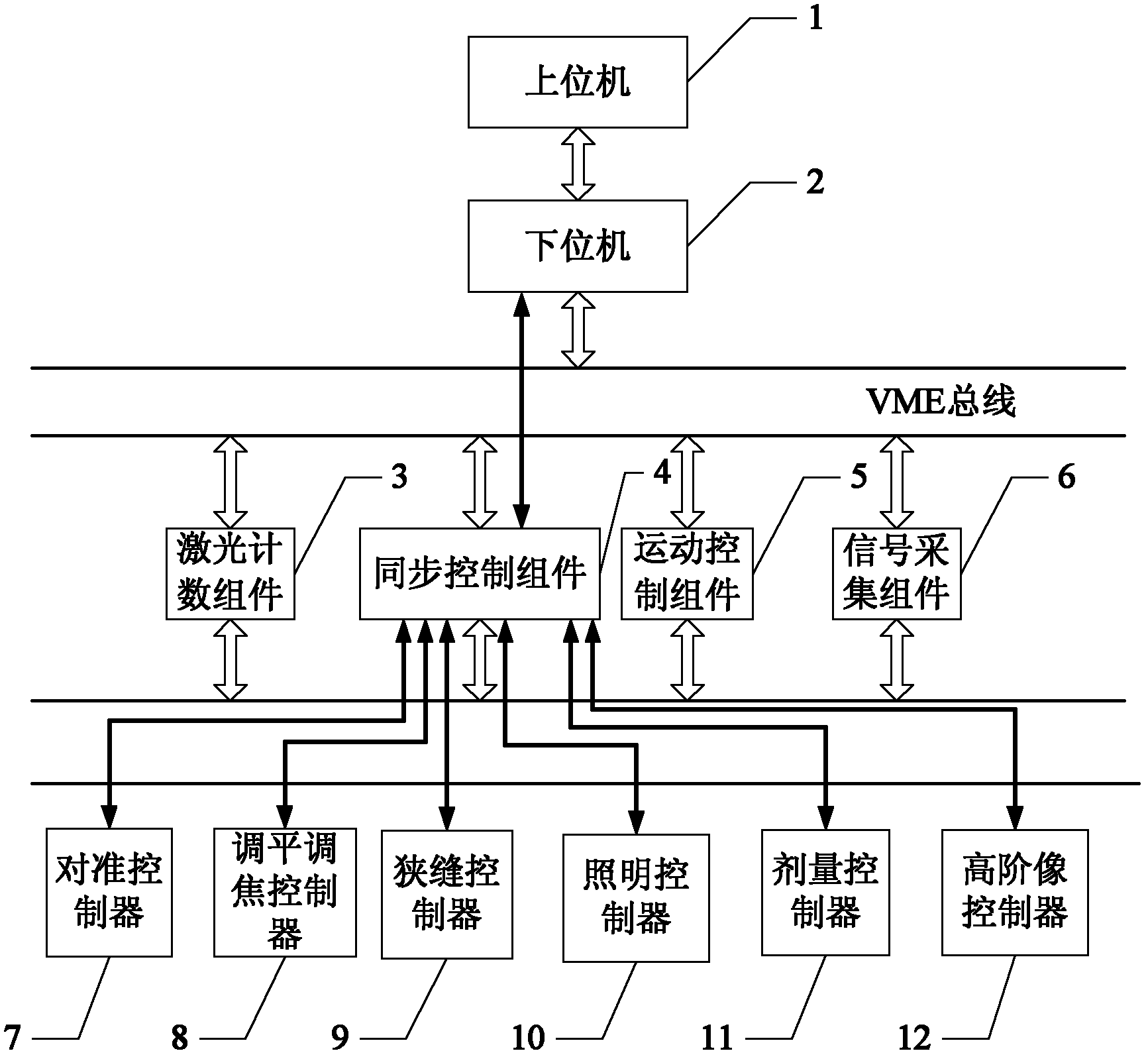
[0022] Specific implementation mode 1. Combination figure 1 Specifically explain this embodiment, the synchronous control system of the step-scan lithography machine based on VME bus, it comprises upper computer 1, lower computer 2, laser counting assembly 3, synchronous control assembly 4, motion control assembly 5 and VME bus, so The motion control assembly 5 described above is composed of a workpiece table controller and a mask table controller,
[0023] The VME bus includes a VME64 custom protocol bus and a VME64 standard bus, and the VME64 custom protocol bus is a user-defined interface of the P2 / J2 port, and the user-defined interface includes an address bus of a 7-bit laser counting component 3 , 36-bit laser counting component 3 data bus, 2 laser counting component 3 sampling signal lines, 1-bit laser counting component 3 clock signal line, 6-bit laser counting component 3 state transmission signal line, 1-bit motion control component 5 data reading signal line, the d...
specific Embodiment approach 2
[0026] Specific embodiment two, combine figure 1 Describe this embodiment in detail, the difference between this embodiment and the synchronous control system of the VME bus-based step-scan lithography machine described in Embodiment 1 is that it also includes a signal acquisition component 6, and the synchronous control component 4 automatically passes through VME64 Define the connection between the bus and the signal acquisition component 6 .
specific Embodiment approach 3
[0027] Specific embodiment three, combine figure 1 Describe this embodiment in detail. The difference between this embodiment and the synchronous control system of the VME bus-based step-scan lithography machine described in Embodiment 1 is that it also includes an alignment controller 7, a leveling and focusing controller 8. Slit controller 9, illumination controller 10, dose controller 11, high-order image controller 12, synchronous control component 4 and alignment controller 7, leveling and focusing controller 8, slit control through optical fiber respectively Controller 9, lighting controller 10, dose controller 11 and high-level image controller 12 are connected.
PUM
 Abstract
Description
Claims
Application Information
 - R&D
- Intellectual Property
- Life Sciences
- Materials
- Tech Scout
- Unparalleled Data Quality
- Higher Quality Content
- 60% Fewer Hallucinations
Browse by: Latest US Patents, China's latest patents, Technical Efficacy Thesaurus, Application Domain, Technology Topic, Popular Technical Reports.
© 2025 PatSnap. All rights reserved.Legal|Privacy policy|Modern Slavery Act Transparency Statement|Sitemap|About US| Contact US: help@patsnap.com


