
Galloping test machine power loading device for transmission tower tension change research

A technology of transmission tower and loading device, which is applied in measurement device, vibration test, machine/structural component test, etc., can solve the problems of main material fracture, transmission tower damage, economic loss, etc., and achieve the effect of reducing vibration and noise

Active Publication Date: 2012-07-25
STATE GRID HENAN ELECTRIC POWER ELECTRIC POWER SCI RES INST +1
View PDF8 Cites 7 Cited by
  • Summary
  • Abstract
  • Description
  • Claims
  • Application Information

AI Technical Summary

Problems solved by technology

When galloping occurs, the dynamic tension of the conductors will cause serious damage to the transmission tower, which may cause wear and tear of the components and breakage of the main material, and cause the continuous collapse of the entire transmission line tower, resulting in huge economic losses.
Since the failure mechanism of the transmission tower under the dynamic tension of the conductor has not yet been clarified, it is necessary to conduct experimental research on the failure mechanism of the transmission tower under the action of the conductor galloping, but there is no one that can reproduce the conductor by exciting the conductor The dynamic loading device acting on the dynamic tension of the tower during galloping cannot accurately simulate the galloping situation of the wire
The existing simulation device is mainly used to analyze the force characteristics of the conductor itself during the galloping process. Usually, the conductor is moved along an elliptical trajectory to test and analyze the force condition of the conductor. Therefore, the overall design of the device does not consider the power transmission. Dynamic force characteristics of towers in dancing process

Method used


Image

  • Galloping test machine power loading device for transmission tower tension change research
  • Galloping test machine power loading device for transmission tower tension change research
  • Galloping test machine power loading device for transmission tower tension change research

Examples


Embodiment Construction

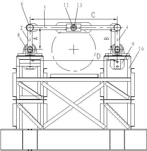
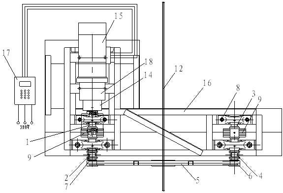
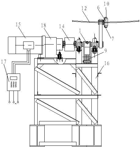
[0025] Such as figure 1 , 2 , 3, the present invention includes a frame 16, a drive mechanism installed on the frame 16 and a parallel four-bar mechanism. The driving mechanism drives the parallel four-bar mechanism to rotate back and forth. The drive mechanism includes a frequency conversion motor 15; the parallel four-bar mechanism includes a driving arm 2, a driven arm 4 and a connecting rod 5, and the driving arm 2, driven arm 4, connecting rod 5 and frame 16 together form a parallel four-bar mechanism.

[0026] The left and right sides of the frame 16 are respectively equipped with a driving shaft 1 and a driven shaft 3, and the driving shaft 1 and the driven shaft 3 are all fixed on the frame 16 through the support bearing 8 and bolts. The other end of the drive shaft 1 is connected to the variable frequency motor 15 through a coupling 14, and the variable frequency motor 15 is fixed on the frame 16 by a screw, and the speed control of the variable frequency motor 15 ...


PUM


Abstract

The invention discloses a galloping test machine power loading device for a transmission tower tension change research. The galloping test machine power loading device comprises a rack, and a driving mechanism and a parallel four-bar mechanism arranged on the rack; wherein the driving mechanism is in drive connection with the parallel four-bar mechanism, and comprises a variable frequency motor; the parallel four-bar mechanism is arranged vertically, and comprises a driving rotating arm, a driven rotating arm and a connecting rod connected between the driving rotating arm and the driven rotating arm; a hollow casing pipe is longitudinally arranged in the middle of the connecting rod; and the variable frequency motor is in control connection with a frequency changer. According to the galloping test machine power loading device for the transmission tower tension change research, the operation frequency and the circular operation radius are adjusted, the conductor galloping with various dynamic characteristics and different amplitudes is simulated, a dynamic tensile force acting on a transmission tower when the ice coated conductor is galloped is reproduced, and a deep research can be carried out on a collapse theory of the transmission tower under the action of the tensile force when the ice coated conductor is galloped.

Description

technical field [0001] The invention belongs to the field of conductor galloping test devices, and in particular relates to a galloping test machine power loading device used for research on tension changes of power transmission poles and towers. Background technique [0002] The galloping of the ice-coated conductor is a kind of large-scale low-frequency vibration that occurs under the action of wind load after the conductor is unevenly covered with ice. When galloping occurs, the dynamic tension of the conductors will cause serious damage to the transmission tower, ranging from wear and tear of the components and fracture of the main material, to the continuous collapse of the entire transmission line tower, resulting in huge economic losses. Since the failure mechanism of the transmission tower under the dynamic tension of the conductor has not yet been clarified, it is necessary to conduct experimental research on the failure mechanism of the transmission tower under the...

Claims


Application Information

Patent Timeline
IPC IPC(8): G01M7/02
Inventor 楼文娟吕中宾杨伦杨威彭鑫南沈国辉张少锋阎东陈勇卢明
Owner STATE GRID HENAN ELECTRIC POWER ELECTRIC POWER SCI RES INST
Learn More