Eureka AIR delivers breakthrough ideas for toughest innovation challenges, trusted by R&D personnel around the world.

Stator component of charging pump for nuclear power station

A technology for nuclear power plants and components, which is applied to the components, pump elements, pumps, etc. of pumping devices for elastic fluids. It can solve the inconvenience of sand cleaning and grinding in the inner flow channel, certain displacement in the axial direction, and high casting difficulty. problems, to achieve the effect of reducing the difficulty of casting process, improving efficiency and reducing processing difficulty

Inactive Publication Date: 2012-07-25
SHANGHAI APOLLO MACHINERY
View PDF2 Cites 0 Cited by
  • Summary
  • Abstract
  • Description
  • Claims
  • Application Information

AI Technical Summary

Problems solved by technology

The inner and outer casings of this structure are mostly integral structures, and the inner casings are mostly fixed at both ends. When the pump is in a thermal transient condition, due to the sudden change in the temperature of the inner casing medium, the pump set, especially the inner casing, will be damaged. Due to thermal expansion and contraction, a certain displacement in the axial direction and other technical problems
In addition, the overall structure of the inner shell will cause the inner runner to be long, which makes it inconvenient to clean and polish the inner runner, and the overall casting is more difficult

Method used


Image

  • Stator component of charging pump for nuclear power station
  • Stator component of charging pump for nuclear power station
  • Stator component of charging pump for nuclear power station

Examples


Embodiment Construction

[0035] In order to better understand the technical solution of the present invention, it will be described in detail below through specific embodiments in conjunction with the accompanying drawings:

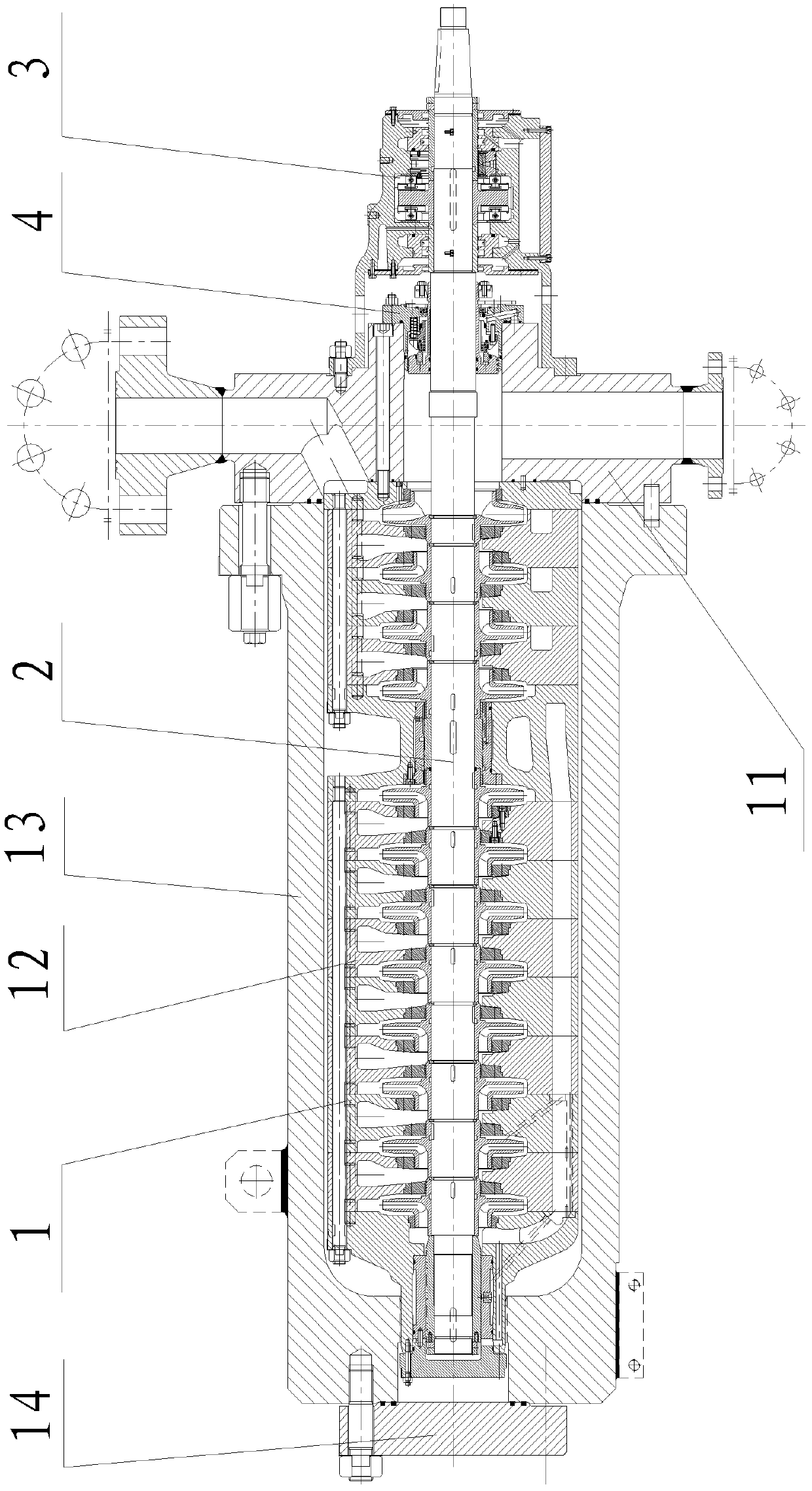
[0036] see figure 1 , The upper charging pump used in nuclear power plants includes a stator part 1, a rotor part 2, a bearing part 3 and a mechanical seal 4.

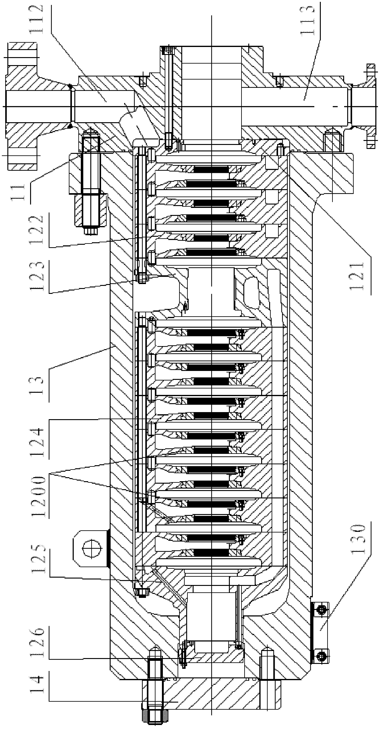
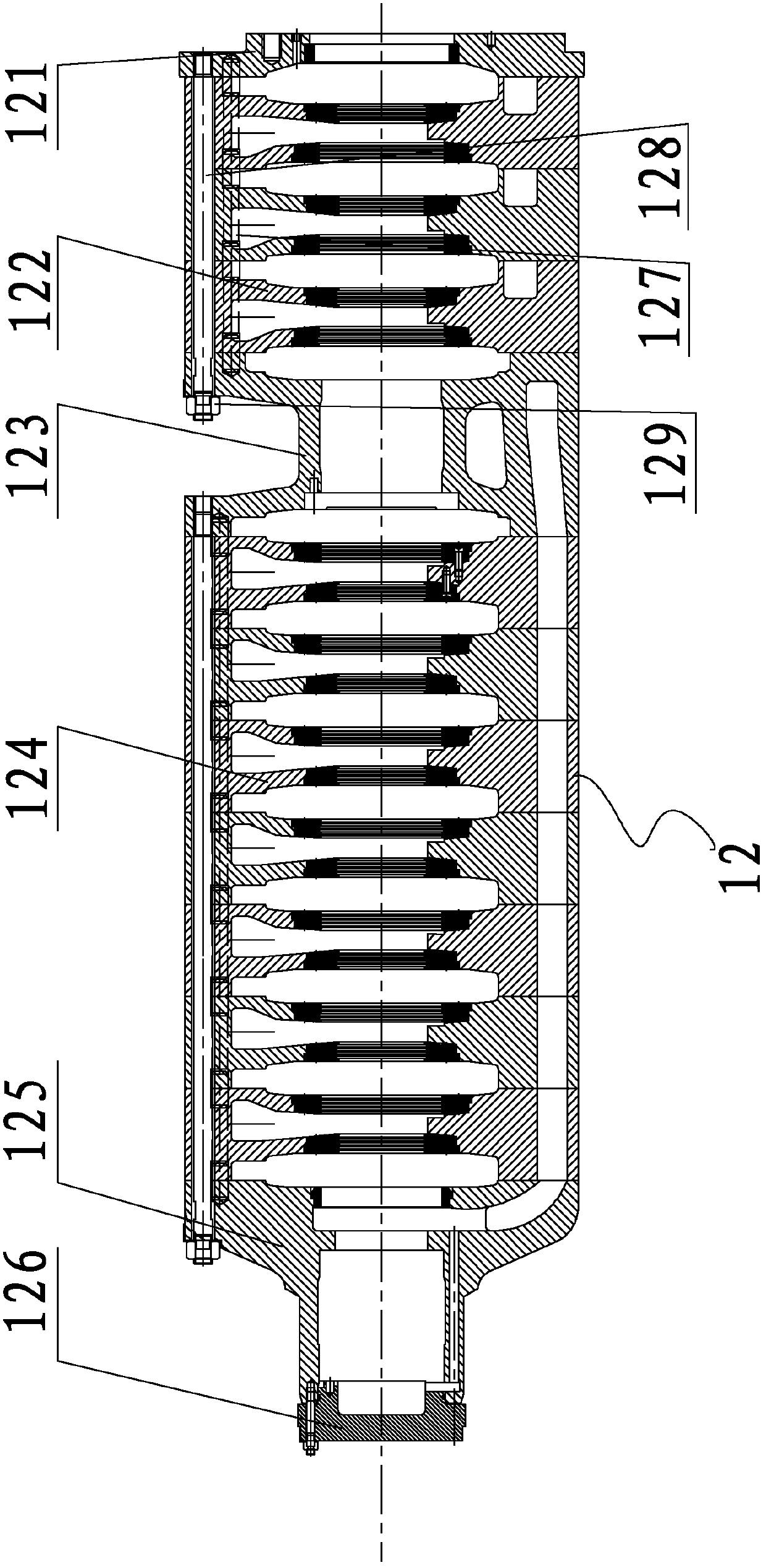
[0037] see again figure 2 , The stator part of the upper charging pump used in the nuclear power plant of the present invention includes a pump head 11, a cylinder body and a tail plate 14 which are sequentially connected back and forth. Among them, the barrel includes an outer shell 12 and an inner shell 13, and a barrel slideway block 130 is provided at the connecting position between the barrel and the pump base to ensure high repositionability of the upper charging pump when disassembled and installed; The components can withstand the axial extension during thermal expansion, without affecting the center of the pum...


PUM


Abstract

The invention discloses a stator component of a charging pump for a nuclear power station, which comprises a pump head, a barrel and a tail plate which are sequentially connected in back and forth direction. The barrel comprises an outer casing and an inner casing. The pump head comprises a main body portion which is of a circular structure and provided with an axial hole, an inlet hole and an outlet hole. An inner cavity of the outer casing comprises an inner casing cavity and a rear bearing cavity. The inner casing is of a radial subdivision structure and comprises a head plate, pump head lateral guiding fluid, a middle section, barrel lateral guiding fluid, a tail cover and a rear bearing cover which are sequentially connected in back and forth direction. After the head plate, the pump head lateral guiding fluid, the middle section, the barrel lateral guiding fluid and the tail cover are connected, complete cavities for containing impellers are arranged at intervals. The head plate is fixed on the rear end face of the pump head to enable the head plate, the pump head lateral guiding fluid, the middle section, the barrel lateral guiding fluid and the front half portion of the tail cover to be located in the inner casing cavity of the outer casing, and the rear half portion of the tail cover and the rear bearing cover are located in the rear bearing cavity of the outer casing and enable the rear end face of the rear bearing cover to have a free space with the front end face of the tail plate.

Description

technical field [0001] The invention relates to an upper charge pump for a nuclear power plant, in particular to a stator component of the upper charge pump for a nuclear power plant. Background technique [0002] The top charge pump is an important part of the chemical and volume control system (RCV), the main functions of the top charge pump are as follows: [0003] 1) Provide upfill water flow to the reactor coolant system to maintain the normal liquid level in the pressurizer; [0004] 2) Provide cooling water to the No. 1 seal of the three reactor coolant pumps, and this water flow also plays a role in preventing high-temperature coolant from leaking through the seal; [0005] 3) Used as a safety injection pump to prevent core exposure in loss of water events (LOCA). [0006] The charging pumps currently used in nuclear power plants are usually horizontal, double-casing multistage centrifugal pumps. The inner and outer casings of this structure are mostly integral st...

Claims


Application Information

Patent Timeline
Patent Type & Authority Applications(China)
IPC IPC(8): F04D29/00F04D29/42F04D1/06
Inventor 陆金琪潘伟红
Owner SHANGHAI APOLLO MACHINERY
Why Eureka
Eureka Blog
Learn More