Hanging type adaptive automatic drill pipe string discharge device
What is Al technical title?
Al technical title is built by PatSnap Al team. It summarizes the technical point description of the patent document.
A discharge device and self-adaptive technology, applied in the direction of drill pipe, drill pipe, drilling equipment, etc., can solve the problems such as inability to provide drilling and tripping operation methods, difficulty in adapting to the drill string gap, and complicated positioning control principles, etc., to achieve structural Compact, fast grabbing, accurate and reliable positioning
Inactive Publication Date: 2012-07-25
JILIN UNIV
View PDF10 Cites 19 Cited by
Summary
Abstract
Description
Claims
Application Information
AI Technical Summary
This helps you quickly interpret patents by identifying the three key elements:
Problems solved by technology
Method used
Benefits of technology
Problems solved by technology
The device realizes the positioning, grasping and moving of the drill string by means of rotary and radial radial telescopic functions. The rotary function can rotate the drill string 360° so that the drill string is aligned with the rotation axis to complete the loading and unloading operation. The invention needs to install a cantilever beam with a central open channel on the second-floor platform, the structure is complicated, the positioning control principle is complicated, and the traditional lifting and lowering operation methods cannot be provided.
The manipulator used in this invention is a horizontal opening and closing type with a large width, so it is difficult to adapt to the narrow drill string gap
Method used
Image
Click on the blue label to locate the original text in one second.
Reading with bidirectional positioning of images and text.
Examples
Embodiment Construction
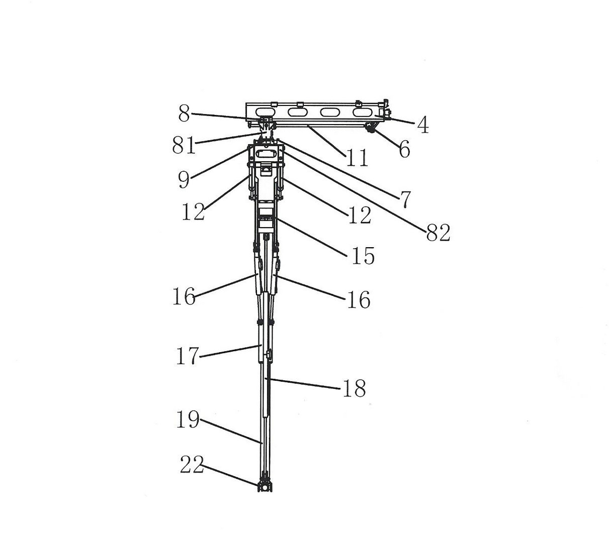
[0034] see figure 1 , figure 2 , image 3 with Figure 4As shown, the present embodiment is composed of a pipe racker guide rail 4, a hydraulic motor 6, a rotary encoder 7, a pulley 8, a worm gear rotary device 9, a screw pair 11, an extension hydraulic cylinder 12, a boom 14, a tripod 15, Composed of deviation correction hydraulic cylinder 16, mast 17, lifting hydraulic cylinder 18, mast inner guide rod 19, manipulator 20, 22, biaxial horizontal inclination sensor 21 and electro-hydraulic proportional control system 13 with PID adjustment function, pipe rower guide rail 4 is fixed At the bottom of the tongue platform 3 of the second-floor platform of the K-type derrick, the tackle 8 is suspended on the guide rail 4 of the pipe racker through the sliding guide block, and the screw pair 11 is arranged under the guide rail 4 of the pipe racker, and the screw pair 11 is connected with the tackle 8 , the hydraulic motor 6 is connected with the lead screw pair 11, the hydrauli...
PUM
Abstract
The invention discloses a hanging type adaptive automatic drill pipe string discharge device, which consists of a pipe string discharger guide track, a hydraulic motor, a rotary encoder, a tackle, a worm gear and worm rotating device, a lead screw pair, an extension hydraulic cylinder, a movable arm, a triangular support, deviation rectifying hydraulic cylinders, masts, a lifting hydraulic cylinder, a mast inner guide rod, a manipulator, a double-axis horizontal inclination sensor and an electro-hydraulic proportional control system with a PID (proportion integration differentiation) adjusting function. The pipe string discharger guide track is fixed at the bottom of a tongue platform of a second-floor platform of a K-shaped derrick, a mounting foundation of the clamping manipulator is a double-layer lifting mast structure, and the external masts are mounted on the triangular support via universal joints and are driven by the two deviation rectifying hydraulic cylinders; the internal masts can slide along the external masts, when a parallelogram stretchable mechanism acts, the internal masts can be driven by the lifting hydraulic cylinder to move vertically, the lifting action of the internal masts can be synchronous to the stretching action, or the lifting action of the internal masts and the stretching action are carried out sequentially definitely, when a drilling rig is connected or disconnected, the internal masts are in a balancing and floating state, and the balancing and floating function is realized by a specific hydraulic loop and a control mode.
Description
technical field [0001] The invention relates to an automatic drilling rod discharge device used in conjunction with a K-type derrick of a land drilling rig, in particular to a suspended self-adaptive automatic drill rod discharge device. It is mainly used for the automatic grabbing, moving and sequential arrangement of the drill string, especially its tilting and side swing functions can adapt to the angle deviation of the drill string discharge, and can automatically carry out automatic drilling in the process of connecting and unloading the drill string. Deviation correction to ensure the sag of the drill string, complete the smooth connection between the drill string, the hole drilling tool and the output shaft of the top drive, so as to realize the automation of the drill string connection, unloading and discharge process. Background technique [0002] In the process of deep well drilling such as oil drilling and continental scientific drilling, tripping and tripping ope...
Claims
Application Information
Patent Timeline
Application Date:The date an application was filed.
Publication Date:The date a patent or application was officially published.
First Publication Date:The earliest publication date of a patent with the same application number.
Issue Date:Publication date of the patent grant document.
PCT Entry Date:The Entry date of PCT National Phase.
Estimated Expiry Date:The statutory expiry date of a patent right according to the Patent Law, and it is the longest term of protection that the patent right can achieve without the termination of the patent right due to other reasons(Term extension factor has been taken into account ).
Invalid Date:Actual expiry date is based on effective date or publication date of legal transaction data of invalid patent.