
Blast furnace reducing tuyere short set

A technology of radial wind and blast furnace, applied in the direction of tuyere, etc., can solve the problems of short service life of tuyere small sleeve, inability to use on demand, and inability to increase air supply speed, etc.

Active Publication Date: 2012-07-25
宗品禾
View PDF7 Cites 1 Cited by
  • Summary
  • Abstract
  • Description
  • Claims
  • Application Information

AI Technical Summary

Problems solved by technology

Although there have been some improved technologies related to the small tuyeres, none of them can increase the air supply speed in real time on demand while keeping the air supply pressure constant during the blast furnace production process.
For example, the Chinese utility model patent with the authorized announcement number CN2797375Y discloses a blast furnace tuyere reducing sleeve, which can be placed in the tuyere to reduce the tuyere area to increase the wind speed, but the reducing sleeve can only be used when the blast furnace is turned on or shut down. When the wind is blowing, put it into the small tuyere cover, which cannot be used as needed during the blast furnace production process
In addition, because the ambient temperature of the small tuyere sleeve is as high as 1500°C-2800°C during operation, the service life of the small tuyere sleeve is short. When the service life is about to expire, the furnace must be shut down to replace the small tuyere sleeve, and the shutdown of the furnace is expensive. Hinder the economic growth of enterprises

Method used


Image

  • Blast furnace reducing tuyere short set
  • Blast furnace reducing tuyere short set
  • Blast furnace reducing tuyere short set

Examples


Embodiment

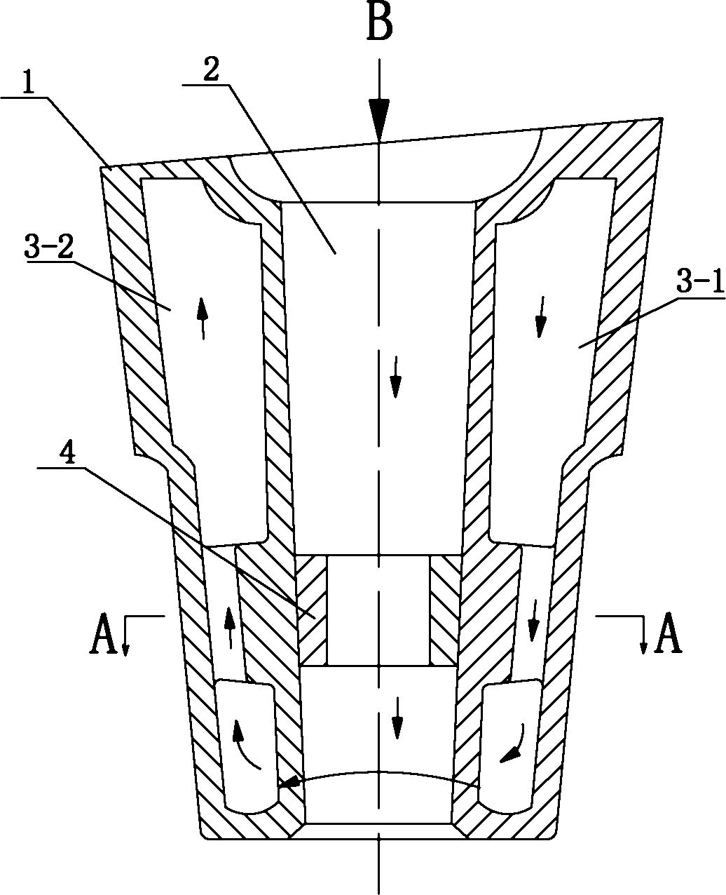
[0016] The basic structure of the blast furnace variable diameter tuyere small sleeve of the present embodiment is as follows: figure 1 As shown, it includes a small sleeve body 1 made of copper or ferrous metal that is basically in the shape of a circular table and has inlet and outlet ends. The tuyere is basically a circular platform-shaped air duct 2, and the air inlet and outlet of the air duct 2 correspond to the air inlet and outlet respectively. The cross-sectional area of ​​the air inlet of the air duct 2 is larger than the cross-sectional area of ​​the air outlet;

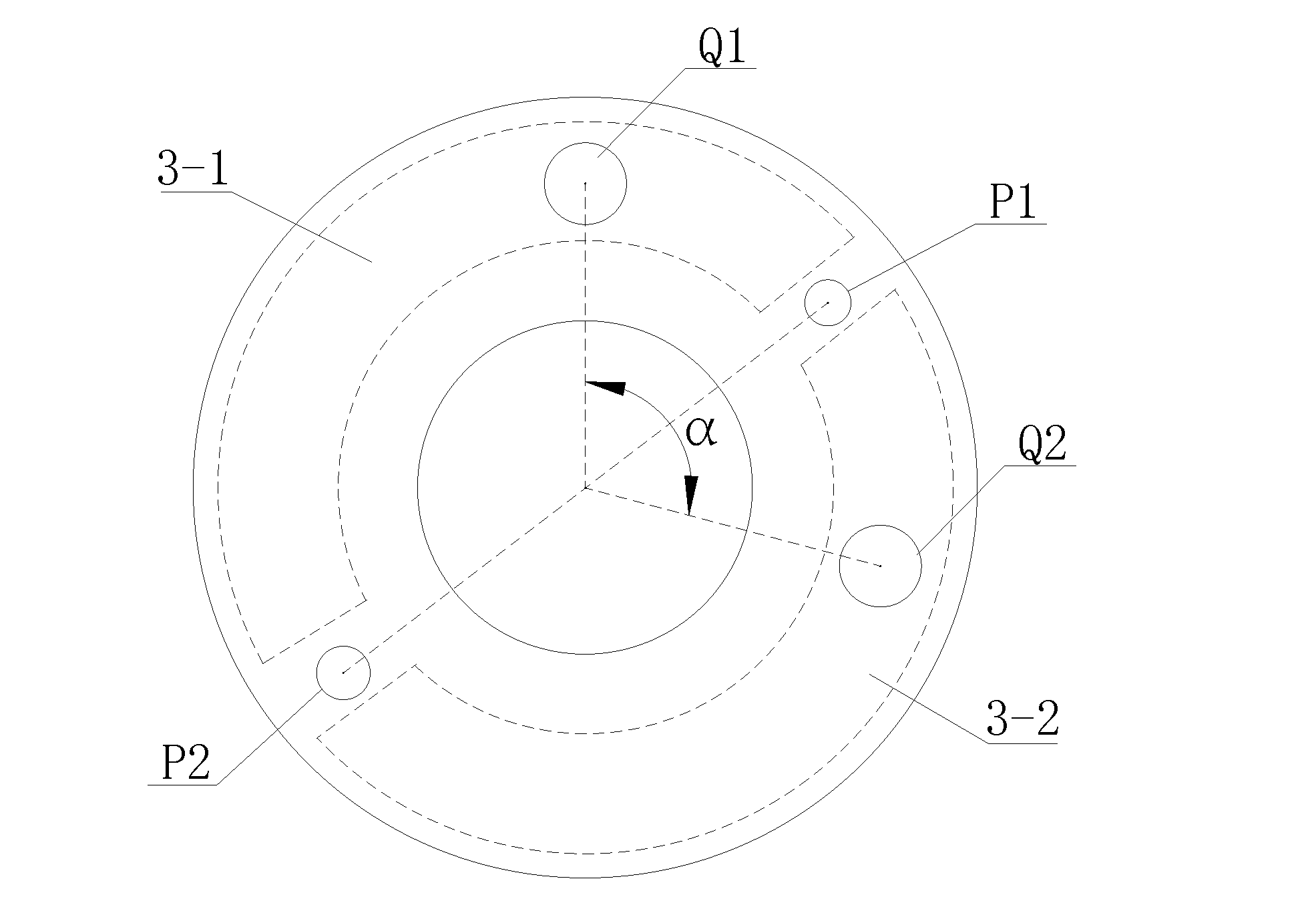
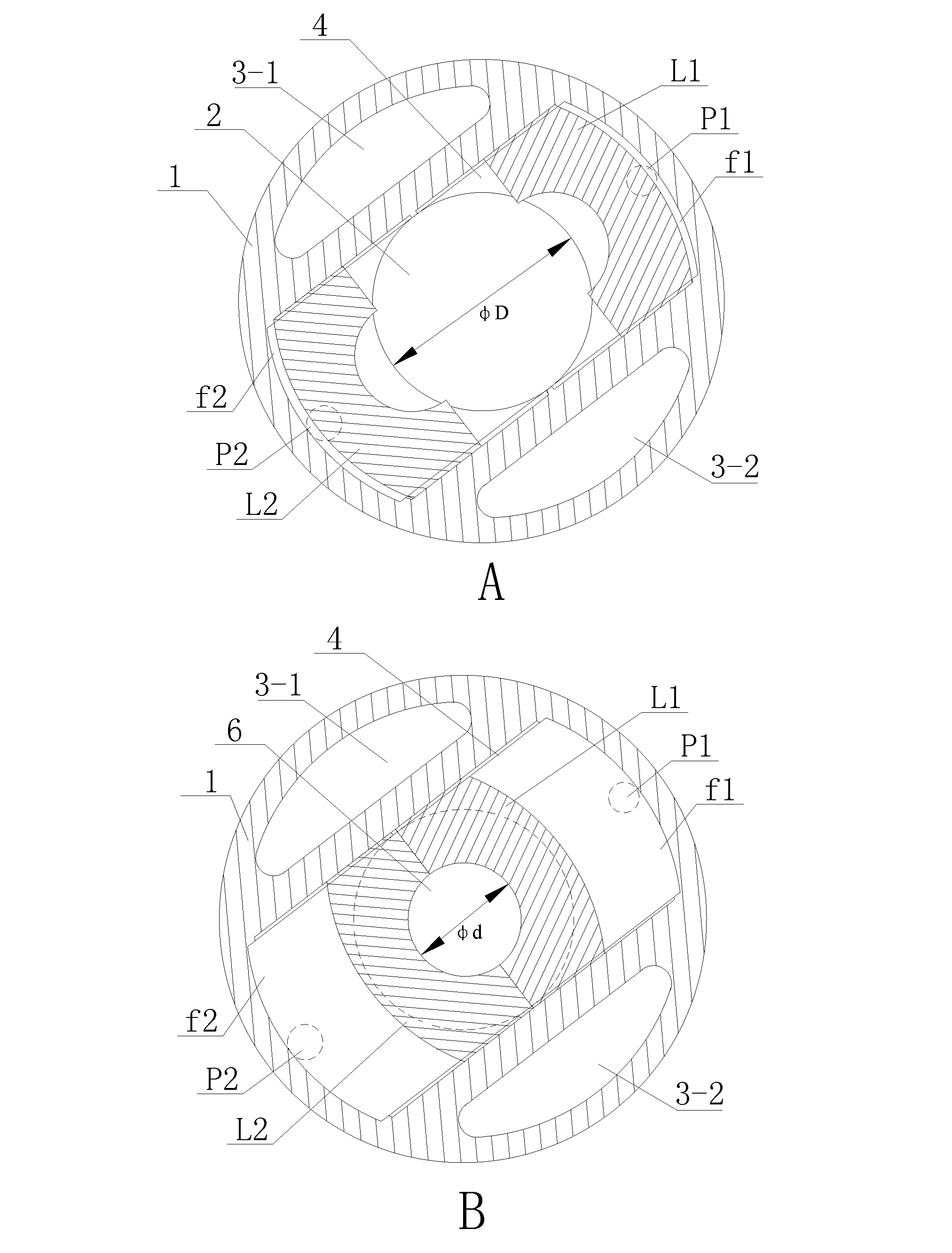
[0017] A valve cavity 4 is provided between the middle part of the small sleeve main body 1 and the air outlet end. Such as figure 2 As shown, the valve cavity 4 is formed by the air duct 2 expanding radially towards the small sleeve body 1 at the same time. The two control holes P1 and P2 at the end; the valve cavity 4 is equipped with a pair of throttle valve cores L1 and L2 respectively located on b...


PUM


Abstract

The invention relates to a blast furnace reducing tuyere short set which comprises a short set body provided with an air inlet end and an air outlet end, wherein the short set is internally provided with an air flue, a valve cavity is arranged between the middle of the short set body and the air outlet end, the air flue expands towards two opposite radial directions of the short set body simultaneously so as to form the valve cavity, the valve cavity is internally provided with a pair of throttle cores, when the pair of throttle cores is at a radial approaching position, the air flue is at the throttle state that a circulation surface is locally covered, when the pair of throttle cores is at a radial separation position, the air flue is at an opening state that the circulation surface is completely opened, and the valve cavity is provided with two control holes capable of controlling the throttle core to move; and the short set is also provided with a cooling channel for cooling the short set. After the structure of the buffer precooling slag liquid pool is adopted, the internal diameter of the tuyere short set can be adjusted in the production process of the blast furnace according to the furnace condition, and blowing-in speed can be improved in real time according to needs under the condition that the constant blowing-in pressure is maintained.

Description

technical field [0001] The invention relates to a small set of variable-diameter tuyeres of a blast furnace, which belongs to the technical field of blast furnaces. Background technique [0002] According to the applicant's understanding, the blast furnace production needs to increase the air supply speed according to the actual demand, so as to improve the blast furnace condition and increase the iron output. Although there have been some improved technologies related to the small tuyeres, none of them can increase the air supply speed in real time on demand while keeping the air supply pressure constant during the blast furnace production process. For example, the Chinese utility model patent with the authorized announcement number CN2797375Y discloses a blast furnace tuyere reducing sleeve, which can be placed in the tuyere to reduce the tuyere area to increase the wind speed, but the reducing sleeve can only be used when the blast furnace is turned on or shut down. When...

Claims


Application Information

Patent Timeline
Patent Type & Authority Applications(China)
IPC IPC(8): C21B7/16
Inventor 宗品禾
Owner 宗品禾
Learn More