
White light LED luminescence apparatus

A light-emitting device, LED chip technology, applied in the direction of electrical components, circuits, semiconductor devices, etc., can solve the problems of short product life, achieve the effect of improving heat dissipation performance and simplifying the packaging process

Inactive Publication Date: 2012-07-18
TSINGHUA UNIV
View PDF3 Cites 4 Cited by
  • Summary
  • Abstract
  • Description
  • Claims
  • Application Information

AI Technical Summary

Problems solved by technology

In addition, the higher the operating temperature of the LED, the shorter its product life. When the operating temperature rises from 63°C to 74°C, the average life of the LED will be reduced by 3 / 4. Therefore, to improve the LED luminous efficiency, its heat dissipation management and design become a very important topic

Method used


Image

  • White light LED luminescence apparatus
  • White light LED luminescence apparatus
  • White light LED luminescence apparatus

Examples


Embodiment 1

[0022] Embodiment 1, white light LED lighting device

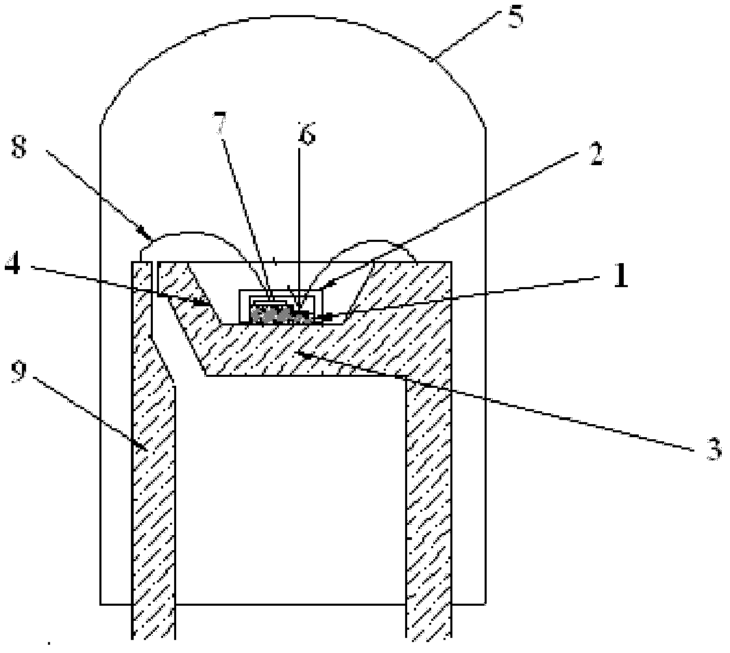
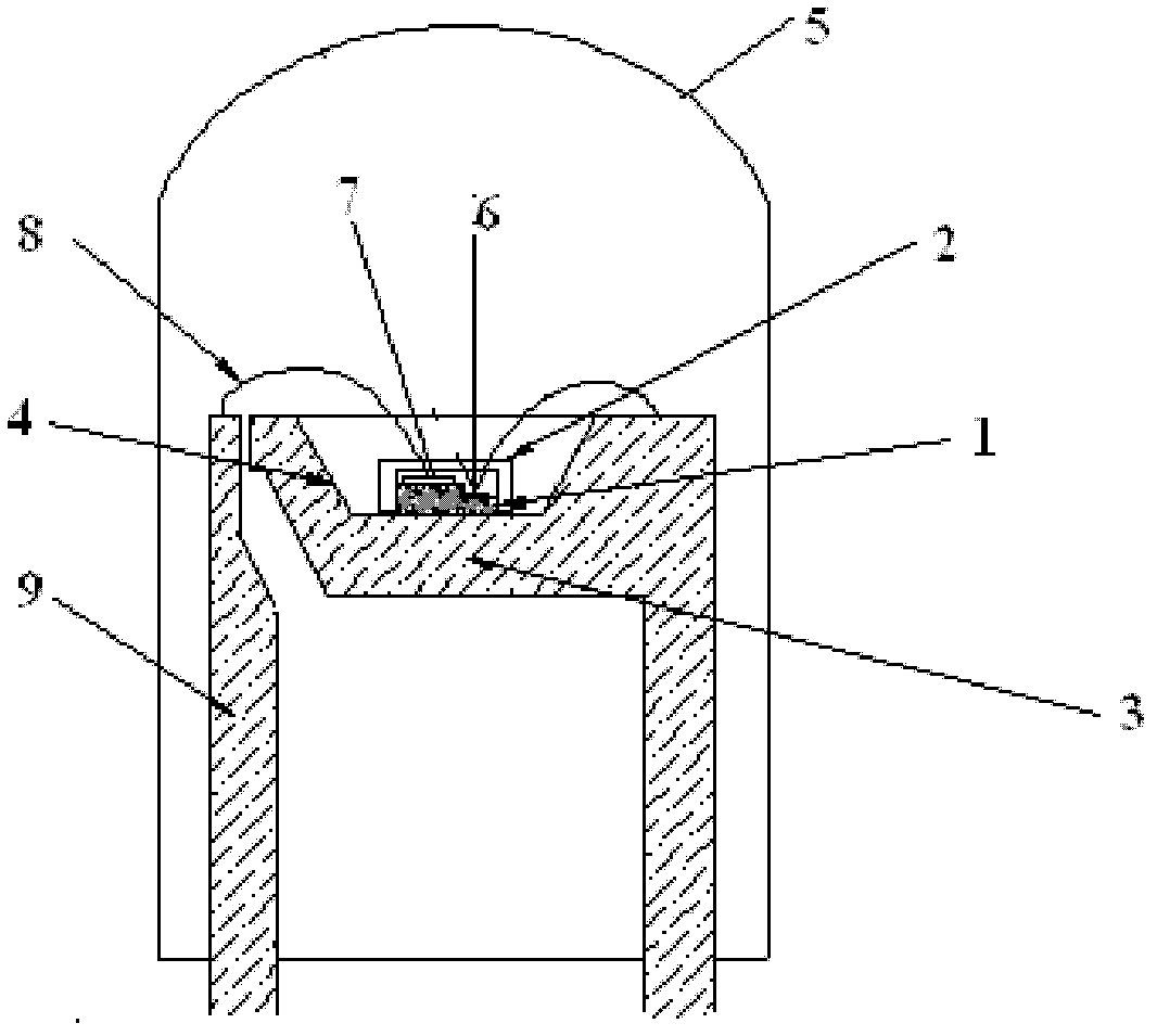
[0023] The white LED lighting device provided in this embodiment includes a blue LED chip 1, a yellow fluorescent LTCC sheet 2, a heat dissipation substrate 3, a reflective cup 4 and a lens 5;

[0024] The heat dissipation substrate 3 is made of LTCC low-temperature co-fired ceramics, which has good heat resistance and high insulation performance; the blue LED chip 1 is bonded to the LTCC low-temperature co-fired ceramic heat dissipation substrate 3, and the substrate of the blue LED chip 1 is sapphire. It is a semiconductor layer composed of N-type nitride, light-emitting layer InGaN and P-type nitride; the electrode on the N-type nitride semiconductor layer of the blue LED chip 1 is the negative electrode 6, and the electrode on the P-type nitride semiconductor layer is the positive electrode 7; The material of the yellow fluorescent LTCC sheet 2 is CaO-B 2 o 3 -SiO 2 :Eu 3+ system (the molar ratio of each component ...

Embodiment 2

[0026] Embodiment 2, white light LED lighting device

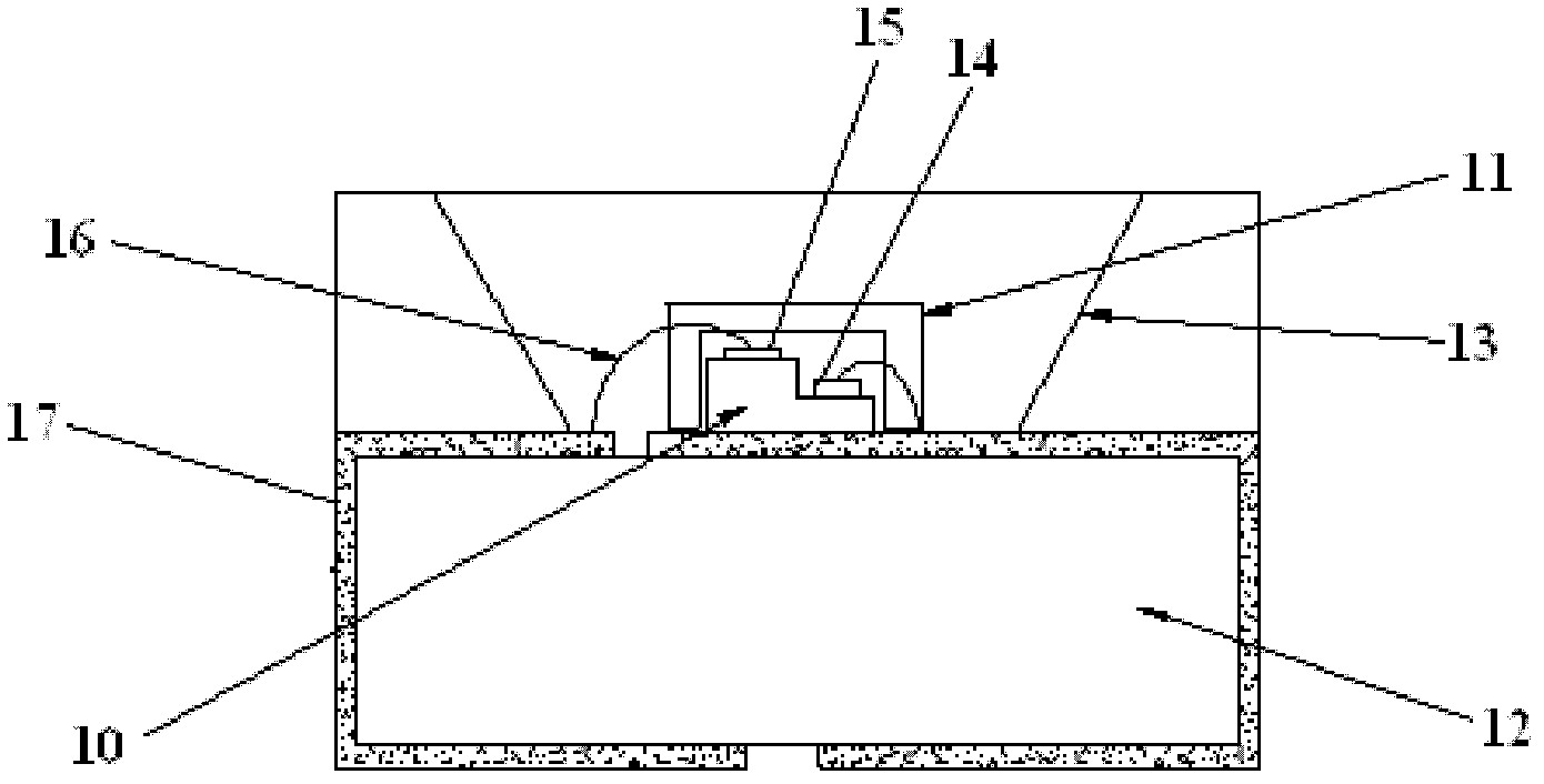
[0027]The white LED lighting device provided in this embodiment includes an ultraviolet LED chip 10, a white fluorescent LTCC sheet 11, a heat dissipation substrate 12 and a reflector cup 13; the heat dissipation substrate 12 is made of LTCC low temperature co-fired ceramics, which has good heat resistance and insulation performance High; the ultraviolet LED chip 10 is bonded on the heat dissipation substrate 12 of LTCC low temperature co-fired ceramics, the substrate of the ultraviolet LED chip 10 is sapphire, which is composed of N-type nitride, light-emitting layer InGaN and P-type nitride The semiconductor layer; the electrode on the N-type nitride semiconductor layer of the ultraviolet LED chip 10 is the negative electrode 14, and the electrode on the P-type nitride semiconductor layer is the positive electrode 15; the material of the white fluorescent LTCC sheet 11 is CaO-B 2 o 3 -SiO 2 : Dy 3+ system (the molar r...


PUM


Abstract

The invention discloses a white light LED luminescence apparatus. The luminescence apparatus comprises an LED chip, a heat radiation substrate, a fluorescence LTCC slice, a reflection cup and an electrode framework. The LED chip is bonded on the heat radiation substrate. The fluorescence LTCC slice is sleeved on the LED chip and coats an upper surface and four side surfaces of the LED chip. The reflection cup is sleeved around the fluorescence LTCC slice. The LED chip is connected to the electrode framework through a leading wire. The material of the fluorescence LTCC slice is a CaO-B2O3-SiO2: RE system or a BaO-TiO2-SiO2-B2O3: RE system. The white light LED luminescence apparatus has the following advantages: firstly, only employing a simple structure-the fluorescence LTCC slice, lots of light of the side surfaces of the LED chip can be outputted and utilized, and since the fluorescence LTCC slice is ceramic material, the apparatus has effects of stabilizing light and controlling light scattering; secondly, since the fluorescence LTCC slice has high thermal conductivity 2-5W / (m*K), through the using of the fluorescence LTCC slice, a heat radiation channel of a whole surface of the chip is realized, and heat radiation performance of a product is improved.

Description

technical field [0001] The invention relates to a white light LED lighting device, belonging to the technical field of LED light sources. Background technique [0002] Diodes (LEDs) using semiconductor PN junctions as light sources came out in the early 1960s. Red LEDs first appeared in 1964, followed by yellow LEDs. It was not until 1994 that blue and green LEDs were successfully developed. In 1996, white LED was successfully developed by Nichia Company of Japan. [0003] No matter from the luminous mechanism and luminous efficiency of LED, or from the development and application speed of this technology, it can be called a brand-new light source, so LED semiconductor light is called "the fourth generation light source". From the point of view of practical application, due to its small size, strong shock resistance, low power consumption, long service life, strong safety and reliability and many other advantages, in a sense, it can be said that its application field and sc...

Claims


Application Information

Patent Timeline
IPC IPC(8): H01L33/64H01L33/50H01L33/62
Inventor 周济李幸运刘世香
Owner TSINGHUA UNIV
Learn More