
PM (particle matter) trapping and back-flushing circulator

A circulator and particulate technology, applied in exhaust gas recirculation, machine/engine, fuel air filter, etc., can solve the problems of increased back pressure of internal combustion engine, high cost, harm to human health, etc., to reduce NOx emissions, eliminate The effect of reducing engine power and purifying the environment

Active Publication Date: 2012-07-18
浙江瑞孚电气有限公司
View PDF3 Cites 2 Cited by
  • Summary
  • Abstract
  • Description
  • Claims
  • Application Information

AI Technical Summary

Problems solved by technology

[0002] In the prior art, in order to reduce the emission of internal combustion engines to pollute the atmospheric environment, especially the emission of PM 2.5 particulates and harmful exhaust NOx from diesel engines, which seriously endanger human health
[0003] Advanced countries in Europe and the United States have legislated in recent years that the particulate filter is an accessory that must be installed for larger power diesel engines. The particulate filter can effectively capture more than 90% of PM 2.5 particles, but its regeneration technology has a complicated structure. Whether it is active regeneration (such as electric heating , fuel injection jet combustion, microwave, infrared heating) or passive regeneration (such as continuous regeneration of fuel additives and catalysts), the regeneration technology device is not only difficult to control, but also high in cost. If the regeneration is not complete, the back pressure of the internal combustion engine will increase, seriously affecting Normal power play of the internal combustion engine
The above factors are the fundamental reasons why these traps are difficult to promote in our country

Method used

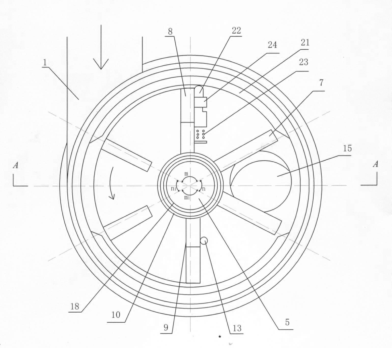

Image

  • PM (particle matter) trapping and back-flushing circulator
  • PM (particle matter) trapping and back-flushing circulator
  • PM (particle matter) trapping and back-flushing circulator

Examples


Embodiment Construction

[0013] The accompanying drawings have shown the structure of the present invention and its embodiments, and further describe the relevant details of the embodiments below in conjunction with the accompanying drawings.

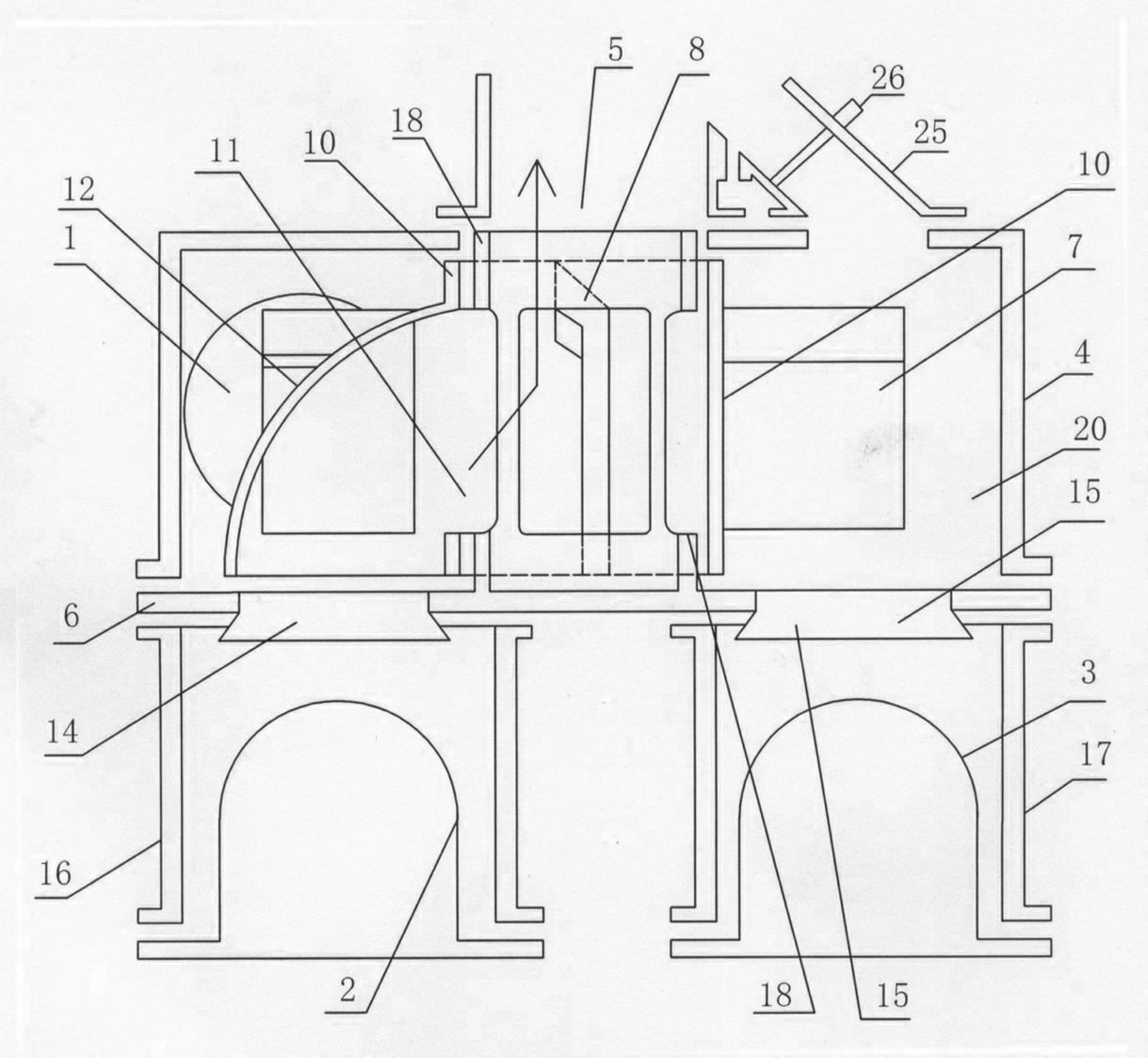
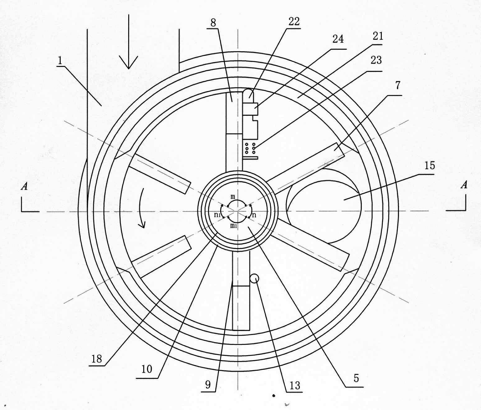
[0014] This microparticle catches blow-back circulator, has a flow conversion chamber 20 that is surrounded by housing 4 and base plate 6, and in the flow conversion chamber there is a uniformly distributed blade 7, 8, 9, etc., paddle (this embodiment 6 paddles), a curved cover plate 12 and a sleeve shaft 10 with an opening on one side form an integral rotating air intake channel 11, and the two ends of the sleeve shaft 10 are sleeved on the tube shaft 18 integrated with the base plate 6, and the sleeve Both ends of the shaft 10 are rotated by means of a tube shaft 18 .

[0015] When the engine starts to inhale, and the air enters from the filter bag assembly 2 on the left side, the particles in the atmosphere are captured on the filter bag assembly 2, and wh...


PUM


Abstract

The invention discloses a PM (particle matter) trapping and back-flushing circulator, comprising a current converting chamber (20) enclosed by a substrate (6) and a shell (4), wherein inside the current converting chamber (20), a rotary air inlet passage (11) is integrated by uniformly distributed paddles (7) (8) (9), a curve cover plate (12) and a shaft sleeve (10); the both ends of the sleeve (10) are connected with a tubular shaft (18) that is integrated with the substrate (6); the paddles (8) (9) on the rotary air inlet passage (11) touch with the spool connecting element (13) of time-control solenoid valve; and the substrate (6) is provided with at least two correspondingly arranged guiding through holes (14) (15), the upper segment of which is connected with the current converting chamber (20), while the lower segment is opened like a horn and connected with the alternate air inlet and outlet tubes (16) (17) and corresponding filter bag assembly (2) (3). The PM particle trappingand back-flushing circulator manufactured according to the subject of the invention can trap over 90% of harmful particles (including PM2.5) discharged from diesel motors and re-combust them to reduce the emission of NOx (nitrogen oxides), which effectively purifies the environment from the source and makes positive contribution to human health. At the same time, the PM particle trapping and back-flushing circulator of the invention also achieves the beneficial effect of energy saving and emission reduction.

Description

technical field [0001] The invention relates to an internal combustion engine intake and exhaust particle capture and blowback cycle technology, in particular to a device invention for a diesel engine intake and exhaust particle capture and blowback cycle technology. Background technique [0002] In the prior art, in order to reduce the emission of internal combustion engines to pollute the atmospheric environment, especially the emission of PM 2.5 particulates and harmful tail gas NOx from diesel engines, which seriously endanger human health. [0003] Advanced countries in Europe and the United States have legislated in recent years that the particulate filter is an accessory that must be installed for larger power diesel engines. The particulate filter can effectively capture more than 90% of PM 2.5 particles, but its regeneration technology structure is complicated. Whether it is active regeneration (such as electric heating , fuel injection jet combustion, microwave, in...

Claims


Application Information

Patent Timeline
IPC IPC(8): F02M35/08F02M25/07F01N3/023F02M26/13
CPCY02T10/121Y02T10/12
Inventor 郑业
Owner 浙江瑞孚电气有限公司
Learn More