
Technology and system for deep removal of tar in biomass gas by coupling adsorption

A biomass gas and tar technology, which is used in gas dust removal, petroleum industry, and the manufacture of combustible gas, etc., can solve the problem of rare application, and achieve the effect of wide adaptability and wide adaptability of raw materials.

Active Publication Date: 2013-12-25
NANJING TECH UNIV
View PDF6 Cites 0 Cited by
  • Summary
  • Abstract
  • Description
  • Claims
  • Application Information

AI Technical Summary

Problems solved by technology

However, the application of adsorption process in biomass gas tar removal process is rare

Method used


Image

  • Technology and system for deep removal of tar in biomass gas by coupling adsorption

Examples


Embodiment 1

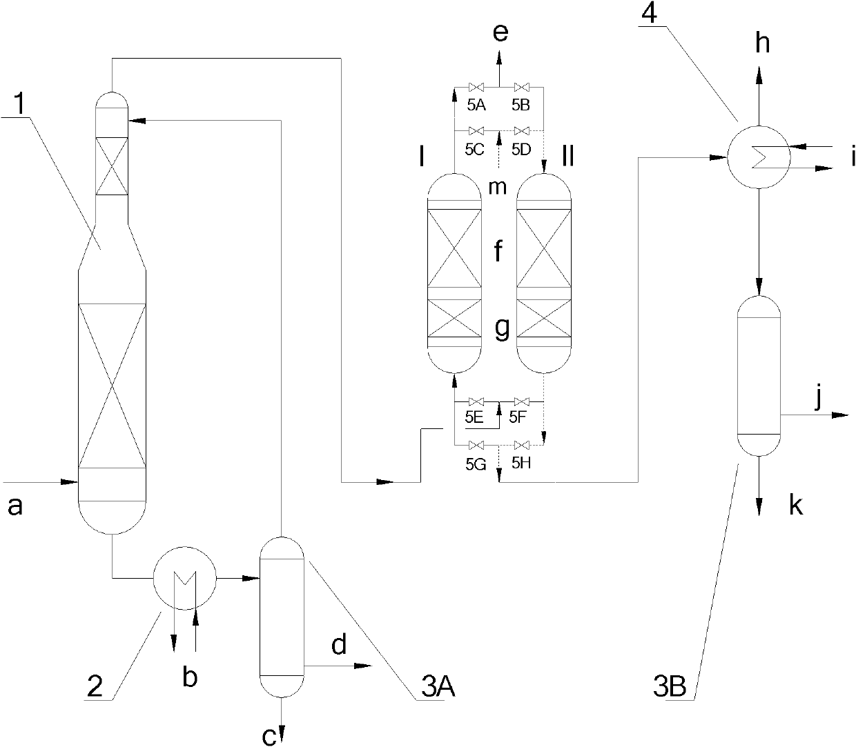
[0029] The schematic diagram of the system of the present invention is as figure 1 Shown, by spray cooling tower 1, cooler 2, condenser 4, the first tar adsorption tower I, the second tar adsorption tower II, heavy tar storage tank 3A, light tar storage tank 3B, first valve 5A, the second The second valve 5B, the third valve 5C, the fourth valve 5D, the fifth valve 5E, the sixth valve 5F, the seventh valve 5G, the eighth valve 5H and pipelines.

[0030] The 500°C high-temperature biomass gas a rich in tar obtained from the biomass gasifier is mainly combustible CO, H 2 Combustible components such as tar, containing tar macromolecular vapor, first enter the spray cooling tower 1 after dust removal, and are sprayed and cooled by heavy tar, and the heat released by condensation is taken away by the heat exchange medium b of cooler 2; the components obtained by condensation are heavier The tar and the residual oil containing more ash enter the heavy tar storage tank 3A at a tempe...

Embodiment 2

[0033] As in the biomass gas detarring system of Example 1, the temperature of the biomass gas is 650°C, and the tar content is 800mg / Nm 3 . The cooling temperature of cooler 2 is 130°C; the lipophilic adsorbent is a mixture of all-silicon Silicalite molecular sieve (20%wt) and activated carbon fiber (80%wt), and the hydrophilic adsorbent is 4A molecular sieve (40%wt) and alumina (60%wt) mixture, the adsorption temperature is 5°C. After purification, the tar dew point of biomass gas is reduced to -5°C, and subsequent use will not condense and corrode equipment.

Embodiment 3

[0035] As in the biomass gas detarring system of Example 1, the temperature of the biomass gas is 600°C, and the tar content is 950mg / Nm 3 . The cooling temperature of cooler 2 is 140°C; the lipophilic adsorbent is a mixture of all-silicon Silicalite molecular sieve (10%wt) and MCM-41 (90%wt), and the hydrophilic adsorbent is silica gel (20%wt) and 13X molecular sieve (80%wt) mixture, the adsorption temperature is 3°C. After purification, the tar dew point of biomass gas is reduced to -10°C, and subsequent use will not condense and corrode equipment.


PUM


Abstract

The invention relates to a technology and a system for deep removal of tar in biomass gas by coupling adsorption, wherein the system is composed of a water cooling tower, a tar adsorption tower, a cooler, a storage tank and auxiliary pipelines and valves. After being dedusted, the biomass gas firstly enters into the water cooling tower to be in spray contact with the heavy tar liquid, and most of the heavy tar steam is cooled and condensed into liquid; the primarily purified biomass gas is conveyed into the tar absorption tower, the light tar steam is fully adsorbed by a lipophilic adsorbent, and the purified biomass gas is conveyed to the subsequent sections for use; the tar adsorption tower desorbs the light tar steam, and respectively obtains the light tar product, the circulatory tail gas containing little light hydrocarbon, and little waste ammonia water after condensation and oil-water separation. The technology for removal of the tar in the biomass gas by coupling adsorption has the characteristic of detarring and dehydrating simultaneously, and can realize the aim of deep removal of the tar; and the technology is low in cost on removal of tar, discharges no waste water, and can produce the byproducts, such as the light tar product and the heavy tar product.

Description

Technical field [0001] The invention relates to a technology and system for deep removal of tar by coupled adsorption of biomass gas, which belongs to the field of high-efficiency utilization of biomass energy. Background technique [0002] Biomass resources are green renewable resources, which can be converted into biomass gas through appropriate thermochemical or biochemical processes, or further processed to obtain chemicals, and provide basic chemical raw materials or energy for the society. [0003] Biomass thermochemical conversion process is a process in which biomass raw materials undergo drying, thermal decomposition, oxidation and reduction stages under high temperature (or auxiliary catalyst) conditions, and macromolecules undergo fragmentation and recombination to convert into small molecular fuel oil or gas. At present, this technology has become one of the main ways to utilize biomass resources, and gasification is the main form of this technology. However, th...

Claims


Application Information

Patent Timeline
Patent Type & Authority Patents(China)
IPC IPC(8): C10K1/04C10K1/02C10K1/00C10K1/32C10J3/84
Inventor 朱跃钊陈海军吴娟廖传华
Owner NANJING TECH UNIV
Learn More