
Sensor arrangement for a vehicle and corresponding method for producing such a sensor arrangement

A sensor device and sensor housing technology, applied in the direction of measuring device, measuring device shell, instrument, etc., can solve problems such as complex maintenance of molds

Active Publication Date: 2012-07-11
ROBERT BOSCH GMBH
View PDF6 Cites 9 Cited by
  • Summary
  • Abstract
  • Description
  • Claims
  • Application Information

AI Technical Summary

Problems solved by technology

Thus, for example, new mold inserts and / or adjustments to the mold inserts may be required, whereby the mold becomes very complex and requires extensive maintenance work

Method used


Image

  • Sensor arrangement for a vehicle and corresponding method for producing such a sensor arrangement
  • Sensor arrangement for a vehicle and corresponding method for producing such a sensor arrangement
  • Sensor arrangement for a vehicle and corresponding method for producing such a sensor arrangement

Examples


Embodiment Construction

[0023] in the attached Figures 1 to 10 In , the same reference numerals consistently denote elements or components that perform the same or similar functions.

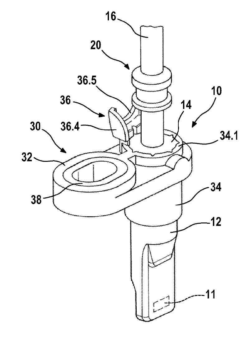
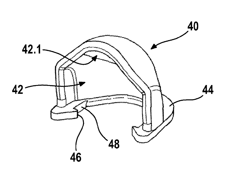
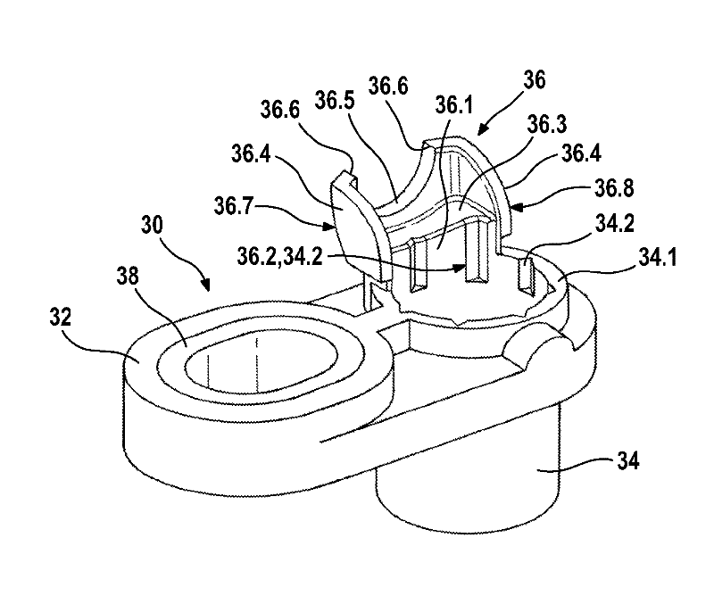
[0024] figure 1 A first exemplary embodiment of a sensor device 1 is shown, which has a sensor element 11 or an electrical subassembly, a mounting plate 30 , a connecting cable 16 for the detection and evaluation of a measurement signal, in particular a magnetic field signal. and cover 40. The sensor element 11 and the connecting cable 16 have been at least partially wrapped with plastic by injection molding to form the sensor housing 10 . The sensor housing 10 is connected to the fastening plate 30 , which comprises a base body 32 with a fastening bushing 38 arranged on the side of the output cable. Furthermore, the fastening backing plate 30 includes a socket 34 connected to the base body 32 , and the sensor housing body 12 of the sensor housing 10 is inserted into the socket 34 . The sensor housing 10 and the s...


PUM


Abstract

The invention relates to a sensor arrangement (1) for a vehicle, in particular for determining a rotational speed and / or a direction of rotation, wherein a sensor element (11) and a connection cable (16) are at least partially encased with plastic by means of injection moulding in order to form a sensor housing (10), and wherein the sensor housing (10) is connected to a fastening tab (30) which comprises a base body (32) having fastening means (38), and to a corresponding method for producing such a sensor arrangement (1). According to the invention, the fastening tab (30) comprises an insertion sleeve (34) which is connected to the base body (32) and into which a sensor housing body (12) of the sensor housing (10) is inserted, wherein the sensor housing (10) and the insertion sleeve (34) each comprise fixing means which are designed in such a manner that there are different angular positions for fixing the sensor housing (10) and the fastening tab (30), wherein the sensor housing (10) and the fastening tab (30) are fixed in one of the different angular positions with respect to one another.

Description

technical field [0001] The invention relates to a sensor arrangement for a motor vehicle of the type according to independent claim 1 and a corresponding method for producing such a sensor arrangement of the type according to independent claim 7 . Background technique [0002] In the laid-open document DE 10 2008 042 091 A1 a method for producing a magnetic field sensor and a corresponding magnetic field sensor is described, which is used in particular as a speed sensor for wheel rotation or for a drive train of a motor vehicle and / or rotation direction sensor. The magnetic field sensor described comprises an electrical subassembly for detecting and evaluating a magnetic field signal as well as a connecting cable, both parts being encased together in plastic during the injection molding process. At the same time, a fastening plate is injected, which has a base body provided with a fastening bush. The described production method uses a proven production method for the produ...

Claims


Application Information

Patent Timeline
Patent Type & Authority Applications(China)
IPC IPC(8): G01P1/02G01D11/30F16M13/02G01D11/24
CPCG01D11/30G01P1/026
Inventor R.施泰因布林克D.马蒂J.贝耶斯多费尔
Owner ROBERT BOSCH GMBH
Learn More