
Method and device for regulating temperature of communication equipment in computer room

A communication equipment and computer room technology, applied in the construction parts of electrical equipment, cooling/ventilation/heating transformation, electrical components, etc., can solve the problems of waste of cold air, overheating of communication equipment, uneven distribution, etc., to achieve strong scalability, Simple and convenient installation, strong practical effect

Inactive Publication Date: 2012-07-11
CHINA TELECOM CORP LTD
View PDF1 Cites 2 Cited by
  • Summary
  • Abstract
  • Description
  • Claims
  • Application Information

AI Technical Summary

Problems solved by technology

[0004] The purpose of the cabinet equipment is different, and the equipment installed in the cabinet is also different, so the calorific value is different. The hot spots in the computer room are not evenly distributed, and the current air-conditioning design is to distribute the cooling capacity evenly to all parts of the computer room, so that The unbalanced heat distribution in the computer room cannot be avoided
It not only causes local overheating of communication equipment but also wastes electric energy
In addition, the existing access network room air conditioners can only effectively control the temperature through forced cooling and natural convection. Due to the limitation of the air supply volume of the air conditioner, a large amount of cooling capacity cannot be accurately delivered to the equipment cabinets, resulting in waste of cold air due to short circuit. , and the large capacity causes insufficient cooling supply of the equipment at the end far away from the air conditioner, resulting in serious heating of the equipment

Method used


Image

  • Method and device for regulating temperature of communication equipment in computer room
  • Method and device for regulating temperature of communication equipment in computer room
  • Method and device for regulating temperature of communication equipment in computer room

Examples


Embodiment Construction

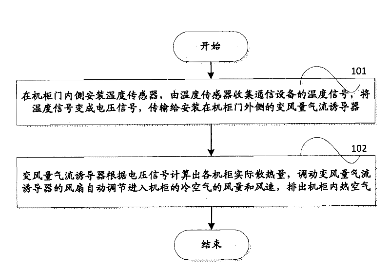
[0025] figure 1 Shown is the method for adjusting the temperature of communication equipment in the computer room according to the present invention, including:

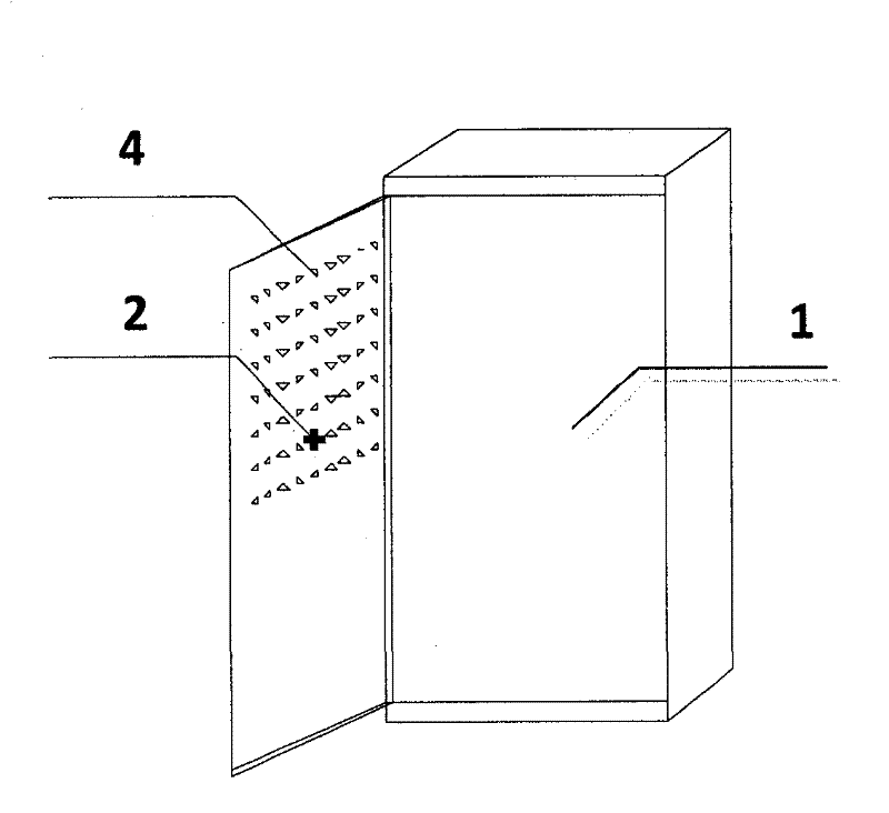
[0026] In step 101, a temperature sensor is installed inside the cabinet door, and the temperature sensor collects the temperature signal of the communication device, converts the temperature signal into a voltage signal, and transmits it to the variable air volume air flow inducer installed outside the cabinet door.

[0027] In step 102, the variable air volume airflow inducer calculates the actual heat dissipation of each cabinet according to the voltage signal transmitted by the temperature sensor, mobilizes the fan of the variable air volume airflow inducer to automatically adjust the air volume and wind speed of the cold air entering the cabinet, and discharges the hot air in the cabinet. The purpose of adjusting the temperature of the communication equipment in the computer room is achieved.

[0028] As an emb...


PUM


Abstract

The invention discloses a method and a device for regulating the temperature of communication equipment in a computer room. Temperature sensors are arranged on the inner sides of cabinet doors, collect temperature signals of the communication equipment, convert the temperature signals into voltage signals, and transmit the voltage signals to variable air volume airflow inductors which are arranged outside the cabinet doors. The variable air volume airflow inductors calculate the actual heat dissipating capacity of each cabinet according to the voltage signals transmitted by the temperature sensors, automatically regulate the air volume and air speed of cold air entering the cabinets through fans of the variable air volume airflow inductors, and exhaust hot air out of the cabinets. Therefore, air is accurately supplied to the communication equipment in the computer room, the temperature of the communication is reduced, and the utilization rate of an air conditioning system is increased.

Description

technical field [0001] The invention relates to the field of energy saving in access network point computer rooms, in particular to a method and a device for adjusting the temperature of communication equipment in the computer room. Background technique [0002] The current communication equipment room is fully enclosed, and the communication equipment in the equipment room is a large heat generating body. To maintain a certain working environment temperature in the equipment room and ensure that the communication equipment operates within the normal temperature range, it is mainly realized by air conditioning equipment. [0003] Air-conditioning equipment in communication equipment rooms is generally divided into two categories: central air-conditioning in large equipment rooms and ordinary split air-conditioning. Because the central air conditioner has air ducts, it is suitable to install a precise air supply system; the split air conditioner has no ducts, and the installa...

Claims


Application Information

Patent Timeline
IPC IPC(8): H05K7/20
CPCH05K7/20836
Inventor 何胜银邱映明
Owner CHINA TELECOM CORP LTD
Learn More