
Control circuit, method and converter for synchronous rectification

A technology of synchronous rectification and control circuit, applied in the field of electronics, can solve the problems of complicated design of synchronous rectification control circuit and increase the cost, and achieve the effect of simplifying the design and reducing the cost

Active Publication Date: 2012-07-11
HUAWEI DIGITAL POWER TECH CO LTD
View PDF3 Cites 17 Cited by
  • Summary
  • Abstract
  • Description
  • Claims
  • Application Information

AI Technical Summary

Problems solved by technology

In this case, when the drive signal of the power switch tube is obtained from the primary side, it is also necessary to set a delay circuit and an isolation circuit to calculate the drive signal of the control tube on the primary side. Therefore, the design of the synchronous rectification control circuit is complicated. and increased cost

Method used


Image

  • Control circuit, method and converter for synchronous rectification
  • Control circuit, method and converter for synchronous rectification
  • Control circuit, method and converter for synchronous rectification

Examples


Embodiment Construction

[0020] The following will clearly and completely describe the technical solutions in the embodiments of the present invention with reference to the accompanying drawings in the embodiments of the present invention. Obviously, the described embodiments are some of the embodiments of the present invention, but not all of them. Based on the embodiments of the present invention, all other embodiments obtained by persons of ordinary skill in the art without creative efforts fall within the protection scope of the present invention.

[0021] It should be noted that in the following description, when two elements are connected, the two elements may be directly connected, or may be indirectly connected through one or more intermediate elements or media. The manner in which two elements are connected may include a contact manner or a non-contact manner, or may include a wired manner or a wireless manner. Those skilled in the art may make equivalent substitutions or modifications to the...


PUM


Abstract

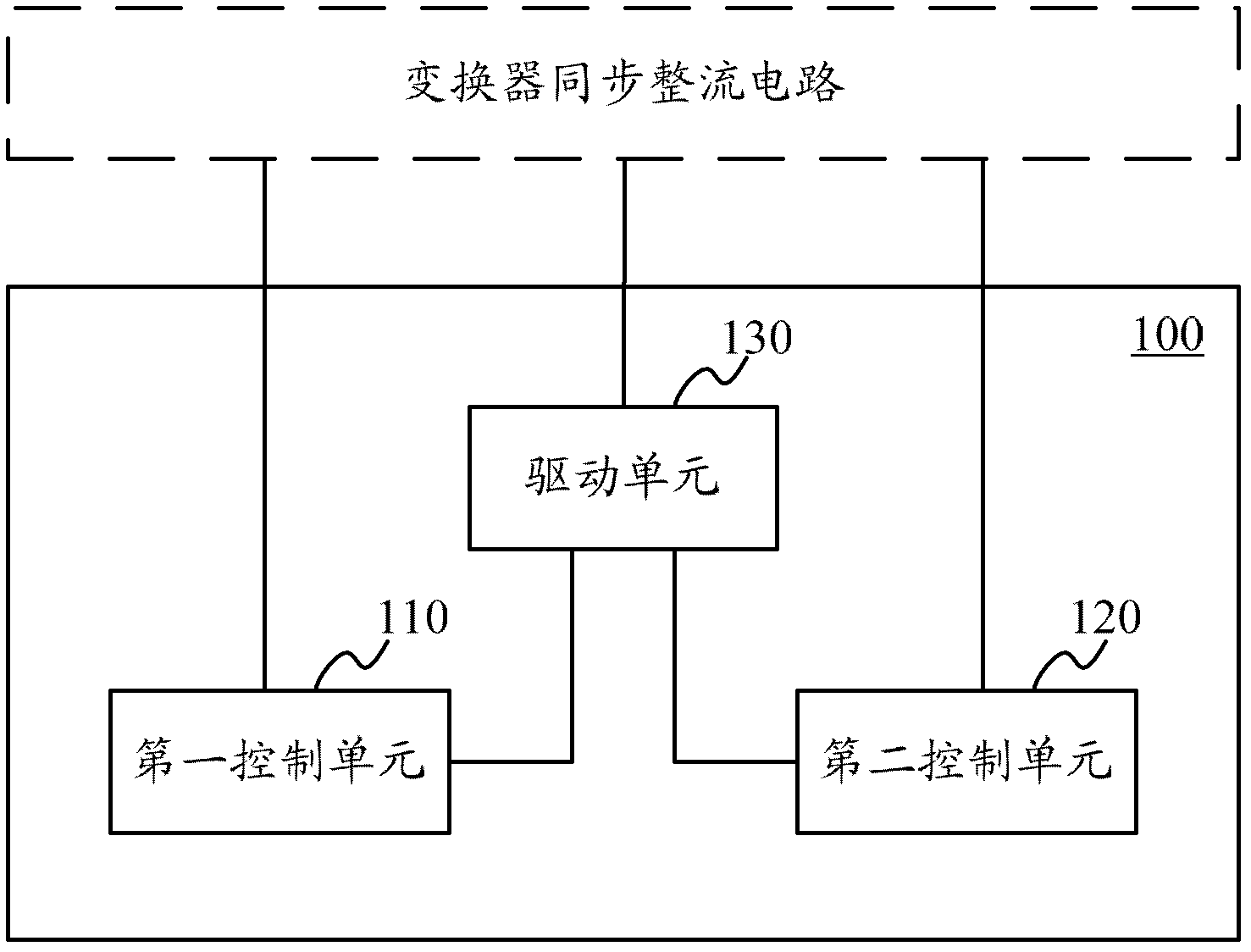
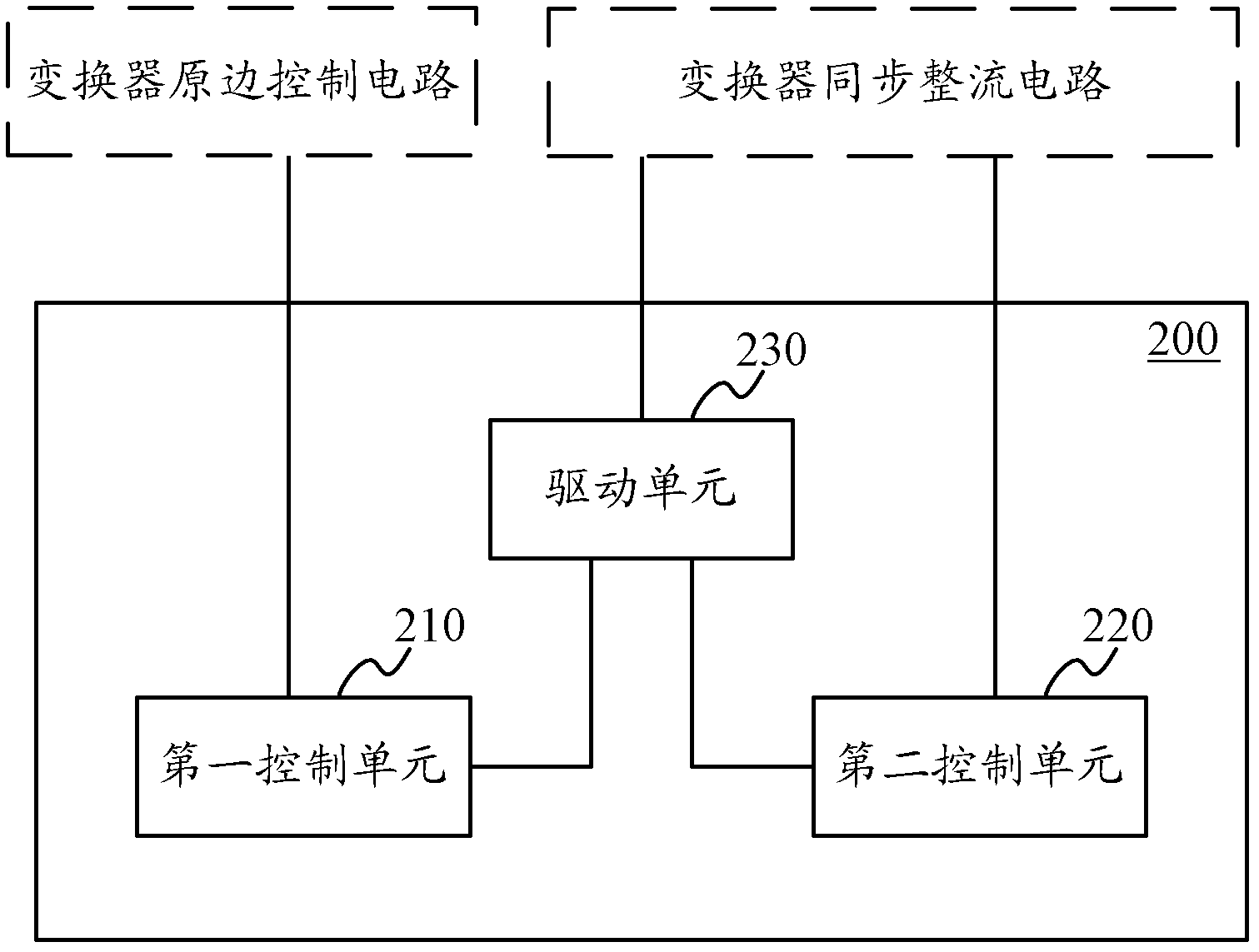
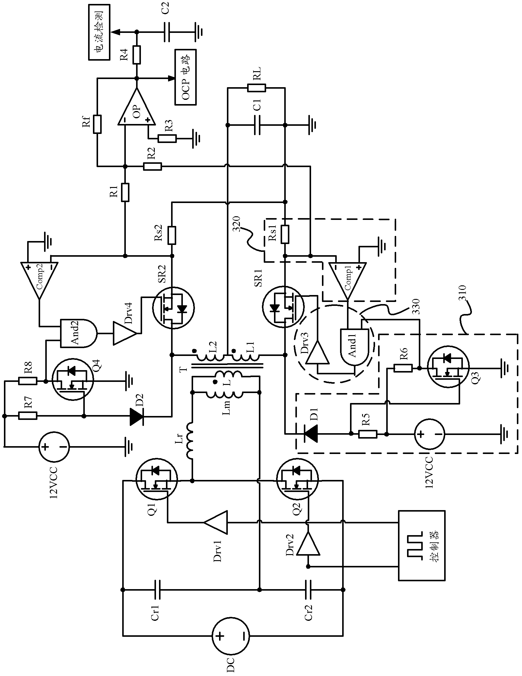
The embodiment of the invention provides a control circuit, a method and a converter for synchronous rectification. The synchronous rectification control circuit comprises a first sampling unit, a second sampling unit and a driving unit, wherein the input end of the first sampling unit is connected with a drain electrode of a synchronous rectifying tube in the synchronous rectification circuit of the converter; the second sampling unit is connected with the synchronous rectification circuit; the first input end of the driving unit is connected with the output end of the first sampling unit, the second input end of the driving unit is connected with the output end of the second sampling unit, the output end of the driving unit is connected to the grid electrode of the synchronous rectifying tube, the first sampling unit is used for acquiring a voltage signal of the drain electrode and carrying out phase reversal so as to output a first control signal, the second sampling unit is used for acquiring a current signal of the synchronous rectification circuit so as to generate a second control signal for switching off the synchronous rectifying tube, and the driving unit is used for AND operation of the first control signal and the second signal so as to generate a driving signal which is used for controlling the synchronous rectifying tube, so that the design of the synchronous rectification control circuit is simplified and the cost is reduced.

Description

technical field [0001] Embodiments of the present invention relate to the field of electronic technology, and more specifically, relate to a synchronous rectification control circuit, method and converter. Background technique [0002] In order to improve efficiency, isolated power supplies such as converters usually use synchronous rectification, and a suitable synchronous rectification control scheme is crucial to realize synchronous rectification efficiently and reliably. [0003] Usually, a current-mode control chip can be used for synchronous rectification control, but the current-mode control chip is expensive and the peripheral circuits are complex. [0004] In addition, a current transformer can also be used to detect the current signal of the synchronous rectification circuit, output the current signal to the latch, and combine the output of the latch with the drive of the power switch tube on the primary side (primary side) of the converter The signals are ANDed t...

Claims


Application Information

Patent Timeline
IPC IPC(8): H02M3/335H02M1/08
CPCY02B70/1475Y02B70/10
Inventor 潘灯海伍元中杨林
Owner HUAWEI DIGITAL POWER TECH CO LTD
Learn More