
Combination type variable speed direct current permanent magnet motor

A permanent magnet motor and combined technology, which is applied in the direction of electric components, electrical components, electromechanical devices, etc., can solve the problems of large torque, large motor volume, and different requirements for motor output speed, and achieve large speed ratio and small volume. Effect

Active Publication Date: 2013-11-06
余姚市兰山电机企业有限公司
View PDF1 Cites 0 Cited by
  • Summary
  • Abstract
  • Description
  • Claims
  • Application Information

AI Technical Summary

Problems solved by technology

[0003] The present invention mainly solves the technical problem that a variety of motors need to be produced to match the motors due to the different requirements of the products on the output speed of the motors, which causes great difficulties in the manufacturing of the motors. The product requires a combined variable speed DC permanent magnet motor to adjust the output shaft speed
[0004] Another object of the present invention is to solve the problems of large volume, heavy mass, small torque and high cost of the existing motors used in food processors, and to provide a combined variable speed DC motor with small volume, light weight, large output torque and low cost. permanent magnet motor
[0005] The third object of the present invention is to solve the problem that the reduction box of the existing food processor matching motor cannot achieve low speed and high torque, and provides a non-equidistant meshing structure and a non-involute in the reduction box Combined variable speed DC permanent magnet motor with asymmetric bevel tooth structure, low speed and high torque

Method used


Image

  • Combination type variable speed direct current permanent magnet motor
  • Combination type variable speed direct current permanent magnet motor
  • Combination type variable speed direct current permanent magnet motor

Examples


Embodiment

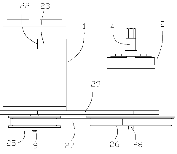
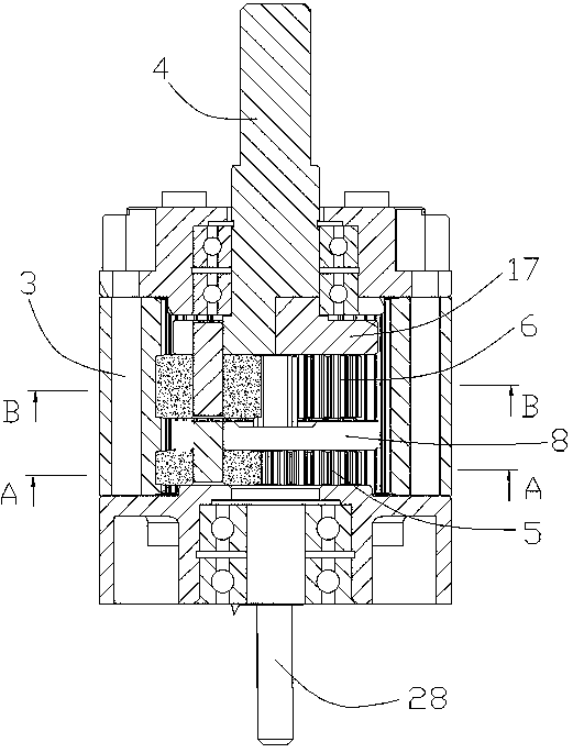
[0025] In this embodiment, a combined variable speed DC permanent magnet motor, such as figure 1 Shown, comprise motor 1 and reduction box 2, motor and acceleration box are all installed on the fixed plate 29, and the motor output shaft 9 of motor passes fixed plate, and driving wheel 25 is installed on the motor output shaft front end; Case input shaft 28 also passes fixed plate, and driven wheel 26 is installed on reduction box input shaft front end, is with synchronous belt 27 on driving wheel and driven wheel, links to each other by synchronous belt transmission.

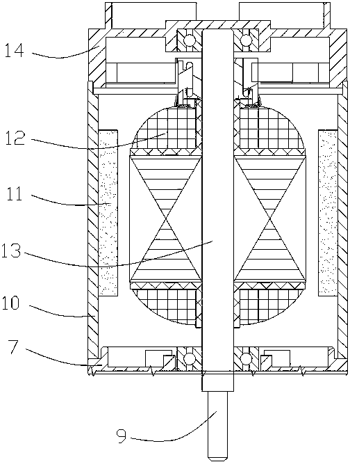
[0026] The motor is a DC permanent magnet motor, such as image 3 As shown, the motor includes a housing, and the housing is composed of a front end cover 7, a motor barrel 10 and a rear end cover 14, and a rotating shaft 13 is arranged in the housing, one end of the rotating shaft is arranged on the rear end cover through a bearing, and the other end of the rotating shaft passes through the front end Cover and...


PUM


Abstract

The invention relates to a combination type variable speed direct current permanent magnet motor, which resolves the problem that products have different requirements for output rotating speed of the motor, various motors are required to be produced to match the products, and the motor is large in size and small in torsion. The motor comprises a motor and a reduction box, a driving wheel is arranged on a motor output shaft of the motor, a driven wheel is arranged on a reduction box input shaft of the reduction box, and the driving wheel and the driven wheel are connected through a belt. The reduction box comprises an inner gear ring, three first-grade planet gears and three second-grade planet gears, wherein the three first-grade planet gears and three second-grade planet gears are meshed in the inner gear ring. The first-grade planet gears and the second-grade planet gears adopt the non-equidistance meshing structure, and inner teeth of the inner gear ring adopt the unsymmetrical non-involute helical-face tooth structure. The combination type variable speed direct current permanent magnet motor adopts the motor in one specification, can conveniently adjust output speed by adjusting the diameter of the driving wheel and the driven wheel and can smoothly pass product mandatory certification. The motor is large in transmission speed ratio, small in volume and capable of conducting a spark test of a commutator.

Description

technical field [0001] The invention relates to a motor, in particular to a combined variable-speed DC permanent magnet motor which can change the output speed according to requirements and meets the requirements of compulsory certification, has the advantages of small size, light weight, good deceleration effect and large output torque. Background technique [0002] The current small household appliance manufacturing enterprises have different requirements for the output shaft speed when designing juice extractors, noodle rolling machines, and meat grinders with various functions. Because the supporting DC permanent magnet motor must be forced by the GB12350 small power motor Certification, during the certification, the speed, reduction ratio, torque, etc. of the motor are clearly specified in the specification and cannot be changed at will. Otherwise, the certificate will be suspended for rectification due to product consistency. It caused great difficulties, and it was im...

Claims


Application Information

Patent Timeline
Patent Type & Authority Patents(China)
IPC IPC(8): H02K7/116H02K5/04
Inventor 罗曰谡闻祖慰
Owner 余姚市兰山电机企业有限公司
Learn More