
Method for manufacturing patterned substrate

A technology for patterning substrates and manufacturing methods, which is applied in semiconductor/solid-state device manufacturing, electrical components, circuits, etc., can solve problems such as increased equipment and production costs, low production efficiency, and lower size limits, and achieves reduced production costs. The effect of improving production efficiency and eliminating photolithography process steps

Inactive Publication Date: 2012-07-11
ENRAYTEK OPTOELECTRONICS
View PDF4 Cites 4 Cited by
  • Summary
  • Abstract
  • Description
  • Claims
  • Application Information

AI Technical Summary

Problems solved by technology

However, the use of photolithography technology has low production efficiency and high cost, and the lower limit of the size of the manufactured pattern will also have certain restrictions.
For example, using photolithography to manufacture nanostructures with light emitting wavelengths similar to LEDs, the cost of equipment and production will be greatly increased.

Method used


Image

  • Method for manufacturing patterned substrate
  • Method for manufacturing patterned substrate
  • Method for manufacturing patterned substrate

Examples


Embodiment Construction

[0017] In order to make the above objects, features and advantages of the present invention more comprehensible, specific implementations of the present invention will be described in detail below in conjunction with the accompanying drawings.

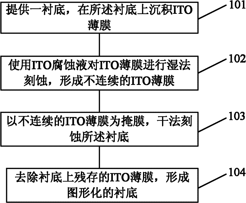
[0018] The fabrication method of the patterned substrate of the present invention comprises the following steps: providing a substrate; depositing ITO on the substrate; using ITO etchant to carry out wet etching to the ITO thin film, to form discontinuous ITO on the substrate surface thin film; use the discontinuous ITO thin film as a mask, dry etch the substrate to form a concave-convex substrate surface; use ITO etching solution to remove the remaining ITO thin film on the substrate to form a patterned substrate.

[0019] The method for fabricating a patterned sapphire substrate of the present invention will be described in more detail below in conjunction with a schematic cross-sectional view, wherein a preferred embodiment of the pr...


PUM

PropertyMeasurementUnit
Thicknessaaaaaaaaaa

Abstract

The invention discloses a method for manufacturing a patterned substrate. The method comprises the followings steps of: providing a substrate; depositing an indium tin oxide thin film on the substrate; carrying out wet-method etching on the indium tin oxide thin film by using an indium tin oxide corrosion solution, so as to form a discontinuous indium tin oxide thin film on the surface of the substrate; taking the discontinuous indium tin oxide thin film as a mask and etching the substrate by a dry method to form a concave-convex substrate surface; utilizing the indium tin oxide corrosion solution to remove the residual discontinuous indium tin oxide thin film from the substrate to form the patterned substrate. The method for manufacturing the patterned substrate, disclosed by the invention, has the advantages of high production efficiency and low cost and is suitable for manufacturing of the small patterned substrate.

Description

technical field [0001] The invention relates to the field of substrate fabrication, and more particularly to a patterned substrate fabrication method. Background technique [0002] Since the manufacture of LED devices generally adopts a lateral structure, the body shape is that the left and right sides of a cuboid are parallel to each other. Although most of the light emitted by the active region exits from the top of the P-type region, due to the large difference in refractive index between the semiconductor material and air, LEDs When light is emitted from a chip with a large refractive index to air with a small refractive index, total reflection will occur at the interface between the semiconductor and the air. Only a small part of the light on the surface of the untreated semiconductor LED structure escapes from the inside of the chip, resulting in The light extraction efficiency of the chip is very low. Since the light extraction efficiency of the chip is the main fact...

Claims


Application Information

Patent Timeline
IPC IPC(8): H01L21/027H01L21/311
Inventor 于洪波肖德元程蒙召张汝京
Owner ENRAYTEK OPTOELECTRONICS
Learn More