
Ultrasonic flaw-detecting machine for steel pipes

An ultrasonic and flaw detector technology, which is applied in the analysis of solids by sound waves/ultrasonic waves/infrasonic waves, material analysis by sound waves/ultrasonic waves/infrasonic waves, and measuring devices. and other problems, to achieve the effect of saving energy consumption, reducing air bubbles, and large water supply

Inactive Publication Date: 2012-07-11
无锡莱林检测机械有限公司
View PDF3 Cites 13 Cited by
  • Summary
  • Abstract
  • Description
  • Claims
  • Application Information

AI Technical Summary

Problems solved by technology

Existing ultrasonic flaw detectors for steel pipes usually adopt a structural form in which the steel pipe is spirally propelled and the ultrasonic probe does not move. Due to the slow propulsion speed of the steel pipe spiral, the detection efficiency of this type of steel pipe ultrasonic flaw detector is low; and the ultrasonic flaw detection must use acoustic coupling media. In the automatic flaw detection equipment, water is used as the coupling medium. The water supply system of the existing ultrasonic flaw detector is slow in water supply, and blisters are easily generated in the detection chamber, which increases the blind area at the end, reduces the flaw detection sensitivity or produces blister interference, thus affecting the detection. Accuracy

Method used


Image

  • Ultrasonic flaw-detecting machine for steel pipes
  • Ultrasonic flaw-detecting machine for steel pipes
  • Ultrasonic flaw-detecting machine for steel pipes

Examples


Embodiment Construction

[0025] The specific implementation manners of the present invention will be further described in detail below in conjunction with the accompanying drawings.

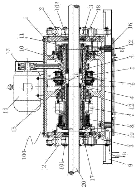
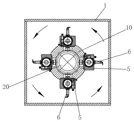
[0026] Such as Figure 1~3 As shown, the present invention includes a flaw detection host 100, a water storage tank and a control system (not shown in the figure), the flaw detection host 100 includes a box body 1, a water tray 9 is provided under the box body 1, and two ends of the box body 1 are provided with There is an inlet 101 and an outlet 102 of the steel pipe to be tested, and a water seal 3 is respectively arranged at the inlet 101 and the outlet 102, and the water seal 3 can prevent water from leaking outwards. The hollow main shaft 10 is rotatably installed in the box body 1 through the bearing 12, and the steel pipe 20 to be tested passes through the hollow main shaft 10, the inlet 101 and the outlet 102 during detection. An adjustable three-wheel centering device 2 is provided at the inlet 101 and the outl...


PUM


Abstract

The invention relates to an ultrasonic flaw-detecting machine for steel pipes. The ultrasonic flaw-detecting machine for the steel pipes is characterized in that: a flaw detection host machine comprises a box body, and two adjustable three-wheel centering devices are arranged at an inlet and an outlet on two sides of the box body respectively; a hollow spindle is arranged in the box body in a rotatable way, and a measured steel pipe passes through the hollow spindle, the inlet and the outlet; and the middle part of the hollow spindle is provided with at least three probe adjustment devices, an ultrasonic probe is arranged on each probe adjustment device, a power generation device and a signal pre-processing device are arranged outside the hollow spindle, and the signal pre-processing device is connected with the ultrasonic probes, and transmits detection data to an ultrasonic flaw detector of a control system by using a wireless signal. A structural form that the steel pipes are linearly pushed and the ultrasonic probes rotate is adopted, so that the pushing speed of the steel pipes is improved, and the flaw detection efficiency is improved; and the centrifugal force produced by the high-speed rotation of the hollow spindle extrudes the air in a detection cavity, and water is supplied by using an interlayer between an inner sleeve and the hollow spindle, so that the water supply quantity is large, bubbles are reduced, and the detection accuracy is improved.

Description

technical field [0001] The invention relates to a device for detecting manufacturing defects of steel pipes by using ultrasonic waves, in particular to an ultrasonic flaw detector for steel pipes, which is used in steel pipe factories to detect the quality of steel pipes. Background technique [0002] In the manufacturing process of steel pipes, due to problems such as slag inclusions in raw materials or loose materials, defects such as cracks and trachoma will occur after the steel pipes are formed. In order to ensure the quality of steel pipe products and reduce potential safety hazards in use, ultrasonic flaw detection equipment is required Steel pipes are tested. Existing ultrasonic flaw detectors for steel pipes usually adopt a structural form in which the steel pipe is spirally propelled and the ultrasonic probe is stationary. Due to the slow propulsion speed of the steel pipe, the detection efficiency of this type of steel pipe ultrasonic flaw detector is low; and the...

Claims


Application Information

Patent Timeline
IPC IPC(8): G01N29/22G01N29/275G01N29/04
Inventor 尤小雷
Owner 无锡莱林检测机械有限公司
Learn More