Radiating pipe base and machining method thereof

A manufacturing method and heat dissipation pipe technology, applied in the direction of tubular elements, heat exchange equipment, lighting and heating equipment, etc., can solve the problems of cost increase, affecting heat dissipation effect, and not meeting economic benefits, etc.

Active Publication Date: 2012-07-11
DONG GUAN HAN XU HARDWARE & PLASTIC TECH CO LTD
View PDF7 Cites 0 Cited by
  • Summary
  • Abstract
  • Description
  • Claims
  • Application Information

AI Technical Summary

Problems solved by technology

[0004] The conventional heat dissipation tube base is also formed by using a heat dissipation tray with a middle hole to be sleeved and combined with a hollow tube base, but the heat dissipation tray and the hollow tube base are two different independent components, so the two components Capillary phenomenon will occur at the joint position and form thermal resistance, so it is not conducive to the absorption and transfer of heat energy and affects the heat dissipation effect
In addition, in order to separately manufacture a heat dissipation tray and a hollow tube base assembly, it not only costs more to open the mold, but also needs to cooperate with the assembly process to complete the combination. On the whole, not only the cost is relatively increased, but also the assembly process must be completed. Spending more processes and man-hours is not in line with economic benefits

Method used


Image

  • Radiating pipe base and machining method thereof
  • Radiating pipe base and machining method thereof
  • Radiating pipe base and machining method thereof

Examples


Embodiment Construction

[0026] The present invention will be further described below in conjunction with the accompanying drawings and specific embodiments.

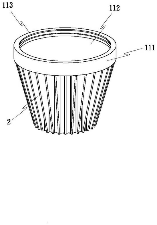
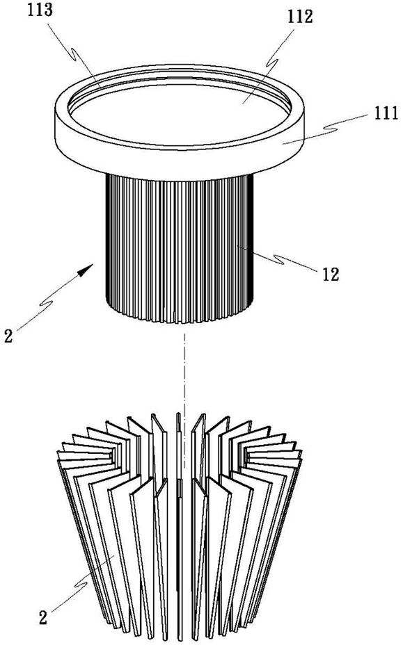
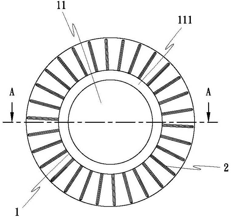
[0027] Such as Figure 1 to Figure 4 As shown, it is the first embodiment of the design of the heat dissipation pipe seat of the present invention, which is integrally formed into a hollow tubular hollow pipe body 1, and the hollow pipe body 1 is provided with an integral body at the front end (or middle position). Connected closed surfaces 11 (such as image 3 , Figure 4 ), and the tube wall is also integrally formed with a plurality of clamping grooves 12 for the surrounding combination of a plurality of heat dissipation fins 2, so that the plurality of heat dissipation fins 2 are tightly fitted and densely inserted into the heat dissipation tube base 1 The peripheral wall is used to form a heat dissipation pipe base 1 with heat dissipation fins 2 .

[0028] The present invention forms the hollow tube body 1, the closed surface 11 and the...


PUM


Abstract

The invention relates to a radiating pipe base and a machining method of the radiating pipe base. The radiating pipe base is provided with a hollow pipe body, a closed surface which is molded with the hollow pipe body by one time and connected with the hollow pipe body integrally is arranged at the front end or the middle section of the hollow pipe body, a plurality of clamp grooves which are molded with the hollow pipe body and the closed surface by one time are arranged on the outer pipe wall of the hollow pipe body and are used for surrounding and combining by a plurality of radiating fins relatively; and the hollow pipe body, the closed surface and the clamp grooves are used for the one-time molding of quantitative aluminum ingot blanks by stamping or extruding (oil pressure). The radiating pipe base is an integral molding assembly, and is formed by one-time processing according to the manufacturing process, the process is simple and convenient, the joint problem and capillary phenomenon can be avoided, and the thermal resistance can not be caused, so that the heat energy can be completely absorbed and transferred, and the radiating effect can be improved.

Description

technical field [0001] The present invention relates to a heat dissipation pipe base design and its manufacturing method, in particular, it is integrally formed into a hollow tubular heat dissipation pipe base, and has an integrally connected sealing surface at the front end or middle position, and multiple molded pipe walls at one time. A clip groove is used for a plurality of cooling fins to surround and combine. Background technique [0002] A conventional radiator with a plurality of radiating fins is composed of a plurality of cooling fins and a heat dissipation pipe base. In order to integrally form a plurality of heat dissipation fins on the outer wall of the heat dissipation pipe base, since the heat dissipation fins The system adopts one-piece molding, so the manufacturing cost is very expensive, and the body thickness of the cooling fins is also quite thick and heavy. Not only the weight load is heavy, but the number of cooling fins is also very sparse, so the heat...

Claims


Application Information

Patent Timeline
Patent Type & Authority Applications(China)
IPC IPC(8): F28F1/12B21D22/02B21C23/02
CPCF21K9/232F21V3/00F21Y2115/10
Inventor 黄崇贤
Owner DONG GUAN HAN XU HARDWARE & PLASTIC TECH CO LTD
Why Eureka
Try Eureka