
Device for measuring cutting force and cutting temperature of cutter holder type rotary milling blade

A temperature measurement and cutting force technology, applied in the direction of measuring/indicating equipment, metal processing equipment, metal processing machinery parts, etc., can solve the problems of short response time, strict requirements on quality and size, high cost, etc., and achieve easy preparation and assembly , high measurement accuracy and low production cost

Inactive Publication Date: 2012-07-11
NANJING UNIV OF SCI & TECH
View PDF9 Cites 40 Cited by
  • Summary
  • Abstract
  • Description
  • Claims
  • Application Information

AI Technical Summary

Problems solved by technology

The above-mentioned milling force measuring device has the following problems: 1. It is easily disturbed by the vibration of the process system; 2. It is difficult to install on site, which often involves the structural improvement of machine tool components; 3. The milling force measuring platform has strict requirements on the quality and size of the workpiece; 4. The measured cutting force is the total cutting force, and the transient change of the cutting force on a single blade cannot be obtained
[0005] In recent years, the method of using magnetron sputtering coating technology and photolithography technology to directly prepare thin-film thermal resistance layer or thin-film thermocouple layer on the rake face of the tool for cutting temperature measurement has the advantages of high test accuracy and short response time (up to tens of nanoseconds), it can contact and measure the cutting temperature change at the designated position in the cutting area (such as the tip of the tool), which is a very potential test method, but the preparation process of the temperature measuring film is complicated, the cost is high, and it is difficult to popularize
[0006] At present, there is no report on the device capable of synchronously measuring cutting force and cutting temperature

Method used


Image

  • Device for measuring cutting force and cutting temperature of cutter holder type rotary milling blade
  • Device for measuring cutting force and cutting temperature of cutter holder type rotary milling blade
  • Device for measuring cutting force and cutting temperature of cutter holder type rotary milling blade

Examples


Embodiment Construction

[0014] The present invention will be further described below in conjunction with the accompanying drawings.

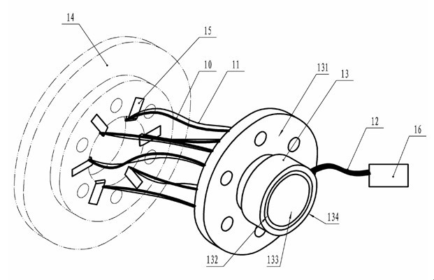
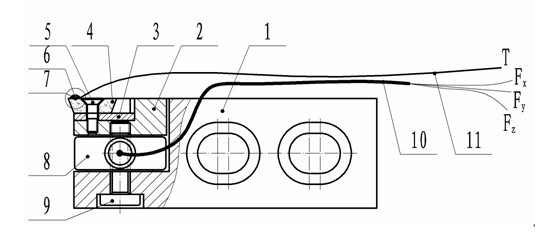
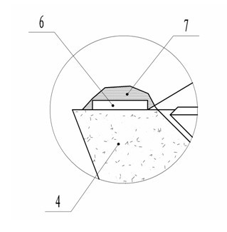
[0015] combine Figures 1 to 3 As shown in the figure, the cutting force and cutting temperature measuring device of the cutter bar type rotary milling insert proposed by the present invention includes a cutter bar 1, a three-way piezoelectric force sensor 8, a film temperature sensitive element 6 and a slip ring 13, and also includes a cutter seat 2. Cutter 3, blade 4, conical screw 5, bolt 9. Among them, the three-way piezoelectric force sensor 8 has a built-in charge amplification circuit, and the thin-film temperature sensitive element 6 adopts a platinum resistance temperature sensitive element.

[0016] combine figure 1 , figure 2 As shown, the signals detected by the three-way piezoelectric force sensor 8 and the thin-film temperature sensitive element 6 are connected to the input interface of the slip ring rotor by cables 10 and wires 11 respectively.

[0...


PUM


Abstract

The invention relates to a measuring device for monitoring cutting force and cutting temperature of various blades for rotary milling processing in a synchronous real-time online manner, which is formed by a three-directional piezoelectric force sensor, a film temperature sensitive element and a slip ring, belonging to the technical field of cutting. According to the invention, a simple and compact cutter holder type structure is adopted; the three-directional piezoelectric force sensor fastened between a cutter seat and a cutter holder by threads is used for measuring the cutting force; the film temperature sensitive element bonded near a cutter tip of a cutting area of a blade is used for measuring the cutting temperature; and a multi-channel through hole type slip ring is used as an electrical interface between a sensing device and a data collecting device. The measuring device has the characteristics of compact structure, excellent dynamic performance, high measuring accuracy, synchronous online measurement of the cutting temperature and the cutting force, easiness in preparation, installation and adjustment and low manufacturing cost, is suitable for synchronous online measurement of transient cutting force and cutting temperature of each cutter on a rotary milling cutter disc, and can also be used for synchronous measurement of the transient cutting force and the cutting temperature in a turning process.

Description

technical field [0001] The invention belongs to the technical field of cutting, and relates to a synchronous real-time measuring device for cutting force and cutting temperature, in particular to a cutting force and temperature measuring device for a cutter bar type rotary milling insert. Background technique [0002] The high-speed hard milling of threaded parts such as lead screws is a precise and efficient enveloping milling process. The cutting force and cutting heat generated during the cutting process have a great impact on the forming accuracy, surface quality and tool life of the workpiece. Important influence, real-time, accurate measurement of transient cutting force and cutting temperature will help to improve the quality of workpiece forming, improve the working state of the tool. [0003] At present, piezoelectric force sensors are generally used for dynamic measurement of cutting force. The structural forms of piezoelectric sensors for measuring milling force a...

Claims


Application Information

Patent Timeline
Patent Type & Authority Applications(China)
IPC IPC(8): B23Q17/09
Inventor 倪寿勇朱红雨李迎冯虎田
Owner NANJING UNIV OF SCI & TECH
Learn More