Hydraulic loop used for controlling accessory head and C shaft and machine tool

A hydraulic circuit and accessory head technology, which is applied in automatic control devices, manufacturing tools, metal processing machinery parts, etc., can solve problems such as inconvenient control, and achieve the effects of small occupied space, high reliability and great flexibility

Inactive Publication Date: 2012-07-11
SANY GRP
View PDF5 Cites 0 Cited by
  • Summary
  • Abstract
  • Description
  • Claims
  • Application Information

AI Technical Summary

Problems solved by technology

In actual operation, the attachment head needs to be controlled by a group of 4 hydraulic cylinders, while the C-axis needs to be controlled by 1 hydraulic cylinder, so all hydraulic cylinders need to work together, and the control is extremely inconvenient

Method used


Image

  • Hydraulic loop used for controlling accessory head and C shaft and machine tool
  • Hydraulic loop used for controlling accessory head and C shaft and machine tool
  • Hydraulic loop used for controlling accessory head and C shaft and machine tool

Examples


Embodiment Construction

[0042] The following will clearly and completely describe the technical solutions in the embodiments of the present invention with reference to the accompanying drawings in the embodiments of the present invention. Obviously, the described embodiments are only some, not all, embodiments of the present invention. Based on the embodiments of the present invention, all other embodiments obtained by persons of ordinary skill in the art without making creative efforts belong to the protection scope of the present invention.

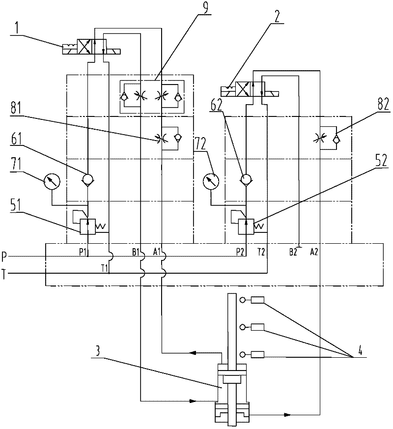
[0043] figure 1 Shown is a schematic diagram of a hydraulic circuit for controlling the attachment head and the C-axis according to an embodiment of the present invention. The hydraulic circuit is used to control the tension of the attachment head and the C-axis of the machine tool, so as to adjust the processing orientation during workpiece processing. from figure 1 It can be seen from the figure that the hydraulic circuit for controlling the accessory head ...


PUM


Abstract

The invention provides a hydraulic loop used for controlling an accessory head and a C shaft and a machine tool. The hydraulic loop comprises a first selector valve, a second selector valve and a hydraulic cylinder. The first selector valve comprises a first oil inlet, a first oil return opening and first working oil ports; the second selector valve consists of a second oil inlet, a second oil return opening and second working oil ports; the hydraulic cylinder can be located at a first position, a second position or a third position, at least three of the first working oil ports and the second working oil ports are connected with the hydraulic cylinder, and the hydraulic cylinder pushes and pulls the accessory head and the C shaft; when the hydraulic cylinder is located at the first position, the accessory head and the C shaft are fastened; when the hydraulic cylinder is located at the second position, the accessory is fastened, and the C shaft is released; and when the hydraulic cylinder is located at the third position, the accessory head is released, and the C shaft is also released. The hydraulic cylinder is used for pushing and pulling the accessory head and the C shaft, and the hydraulic loop and the machine tool have the advantages of small occupied space, compact structure, easiness in control, high reliability and the like.

Description

technical field [0001] The invention mainly relates to the field of machine tools, in particular to a hydraulic circuit for controlling an accessory head and a C-axis, and a machine tool including the hydraulic circuit. Background technique [0002] The attachment head of the machine tool is set on the main shaft, and the cutting direction of the tool can be changed through the attachment head; the C-axis is a rotary joint that performs circular motion along the Z direction (perpendicular to the ground direction). In the process of machining workpieces by machine tools, it is often necessary to tighten the attachment head and the C-axis in order to adjust the machining orientation. [0003] In the prior art, the attachment head and the C-axis of the machine tool are controlled by different hydraulic cylinders to respectively realize the tightening and loosening of the attachment head and the C-axis, which takes up a lot of space. Also, generally during machining, the attach...

Claims


Application Information

Patent Timeline
IPC IPC(8): B23Q15/22B23P23/02
Inventor 刘津津李宗锦杜波
Owner SANY GRP
Why Eureka
Try Eureka