Tiled butting type ingot mold and casting method thereof

A technology of tiling butt joint and ingot mold is applied in the field of casting molds for ferroalloy production, which can solve the problems of hidden dangers, inconvenient installation of ingot molds, erosion and erosion, etc., and achieve the effect of ensuring safety performance and reducing labor intensity of workers.

Active Publication Date: 2013-11-13
四川川投峨眉铁合金(集团)有限责任公司
View PDF1 Cites 0 Cited by
  • Summary
  • Abstract
  • Description
  • Claims
  • Application Information

AI Technical Summary

Problems solved by technology

However, we also found that this cast iron ingot mold also has some structural defects in actual use: the main reason is that there is no flow iron groove on the mold wall around its casting cavity, and the cast iron ingot mold can only be placed on the casting site individually , it is necessary to continuously move the molten iron ladle on the crane to pour the independently placed cast iron ingot molds one by one
However, since the flow iron trough protrudes from the outer end face of the mold wall and is successively placed against the mold wall of the next ingot mold to form a stepped arrangement structure, the uppermost ingot mold will be at a higher position, and the operation of installing the ingot mold is very difficult. It is inconvenient, and there is also a big safety hazard. The molten iron flowing from top to bottom during pouring will cause serious erosion and erosion to the lower ingot mold and damage the ingot mold

Method used


Image

  • Tiled butting type ingot mold and casting method thereof
  • Tiled butting type ingot mold and casting method thereof
  • Tiled butting type ingot mold and casting method thereof

Examples


Embodiment Construction

[0036] Embodiments of the present invention are further described below in conjunction with the accompanying drawings:

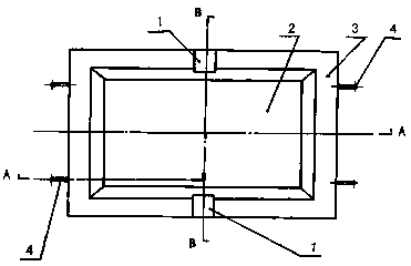
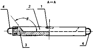
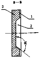
[0037] A flat butt joint ingot mold, which is mainly composed of a mold body 3 and a set of hoisting rings 4 fixedly installed on the mold body 3, and the inner end of the hoisting ring 4 is set as a pawl structure 5, which has good installation and stability performance , said one set of hoisting rings 4 can be installed on the outer end surface position of the mold body 3, and a set of hoisting rings 4 can also be installed on the top surface position of the mold body 3, and the said mold body 3 is provided with an inner wall surface to form an outer inclined structure The casting cavity 2 has a length of 2000mm, a width of 1200mm, and a depth of 200mm, and the controlled external inclination angle α is 135o. A molten iron overflow groove 1 is respectively arranged on the opposite side wall of the cavity 2, and a molten iron overflow groove 1 can also be a...


PUM

PropertyMeasurementUnit
lengthaaaaaaaaaa
depthaaaaaaaaaa
lengthaaaaaaaaaa

Abstract

The invention provides a tiled butting type ingot mold and a casting method thereof. The tiled butting type ingot mold mainly comprises a mold body and a set of hoisting rings fixedly arranged on the mold body, wherein an outward-inclined structure is arranged on the inner wall of a casting concave cavity of the mold body, melted iron overflow grooves are arranged on the top end face of the cavity wall of the casting concave cavity, a set of ingot molds can be formed into a butting type arrangement structure on a supporting guide rail or an I-shaped steel on a smooth working plane according to a tiled installation mode, namely side end faces abut against each other side by side and the melted iron overflow grooves are abutted joint and communicated with each other, and casting operation is carried out according to the steps of smoothing the working plane, installing the ingot molds, pouring molten iron, dumping iron, water quenching, hardening, crushing processing and the like, and the melted iron stably overflows along the horizontally-butted overflow grooves in sequence for the pouring operation, therefore, the washout and erosion effects of the melted iron on the inner wall of the casting concave cavity can be alleviated and the operation difficulty of ingot mold manufacture and arrangement installation can be reduced. The tiled butting type ingot mold and the casting method provided by the invention have the outstanding advantages that the design is novel, the structure is reasonable, the manufacturing is easy to realize, the installation and use are convenient, the service life is long and the safety performance is high.

Description

technical field [0001] The invention relates to a casting mold for producing ferroalloy, and relates to its casting method, in particular to a tiled butt joint ingot mold and its casting method, which is a further improvement and perfection of the current casting ingot mold and its casting method. Background technique [0002] During the development process of the production and smelting of ferroalloys in my country's metallurgical industry, various production methods such as "pit casting", "pit-cast iron block casting" and "sand mold casting" have been experienced in the casting process. Repeated operations of "modeling and modeling" in a high-temperature environment, the working environment is relatively harsh, the cast alloy block is thick, the subsequent crushing process is difficult, and a large amount of alloy particles will be produced during manual and mechanical crushing operations. This will seriously affect the production efficiency and economic benefits of ferroall...

Claims


Application Information

Patent Timeline
Patent Type & Authority Patents(China)
IPC IPC(8): B22D3/00
Inventor 唐华应吴孝郑再春郑惠丽
Owner 四川川投峨眉铁合金(集团)有限责任公司
Why Eureka
Try Eureka