
Process and device for flue gas wet desulphurization using carbide slag or white clay as desulfurizing agent

A technology of wet desulfurization and calcium carbide slag, which is applied in the field of air pollution control technology, can solve the problems of slurry scaling, blockage of equipment, and affecting the use value of desulfurization gypsum, and achieve the effects of reducing sewage discharge and saving water costs

Active Publication Date: 2012-07-11
ZHEJIANG TIANLAN ENVIRONMENTAL PROTECTION TECH
View PDF2 Cites 12 Cited by
  • Summary
  • Abstract
  • Description
  • Claims
  • Application Information

AI Technical Summary

Problems solved by technology

However, white mud also contains reducing substances such as phosphides and sulfur anions, which can easily prevent the oxidation of calcium sulfite. At the same time, due to the presence of sodium ions, the pH value of the slurry rebounds quickly, which easily leads to scaling and blockage of the slurry inside the nozzle and equipment. equipment
[0008] Because calcium carbide slag and lime mud contain many complex components, calcium carbide slag and lime mud cannot be directly applied to the device of limestone-gypsum desulfurization process
Al contained in carbide slag and lime mud 2 o 3 , SiO 2 During the desulfurization process, colloidal suspensions such as calcium silicate and aluminum hydroxide will be formed to fill the entire slurry system. After these colloidal suspensions enter the belt filter with gypsum, a dense film will be formed on the surface of the gypsum. The air permeability of the gypsum cake is reduced, making it difficult to dehydrate the belt filter, resulting in a high moisture content of the gypsum after dehydration, and the heavy metals contained in the water in the slurry are also attached to the inside, which affects the use value of the desulfurized gypsum

Method used


Image

  • Process and device for flue gas wet desulphurization using carbide slag or white clay as desulfurizing agent
  • Process and device for flue gas wet desulphurization using carbide slag or white clay as desulfurizing agent
  • Process and device for flue gas wet desulphurization using carbide slag or white clay as desulfurizing agent

Examples


Embodiment 1

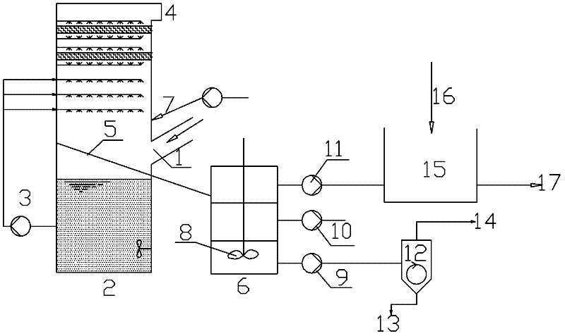
[0034] In a thermal power plant, two 240t / h boilers adopt the device and process of the present invention. The overall installation angle of the draft pipe is at an angle of 60° to the central axis of the absorption tower, and the cross-sectional area of ​​the groove opening is 2% of the cross-sectional area of ​​the absorption tower. The pH value of the desulfurization slurry in the tower is controlled between 5.0-5.4, and the desulfurization liquid-gas ratio is 8L / m 3 , the volume stirring power in the separation tank is 0.04KW / m 3 . The concentration of sulfur dioxide in the imported flue gas is 4300mg / m 3 , the outlet flue gas sulfur dioxide concentration is 96mg / m 3 , the purity of gypsum is 97.2%, the moisture content of gypsum is 9.5%, and the content of heavy metal ions in gypsum is 0.01%.

Embodiment 2

[0036] In a thermal power plant, two 130t / h boilers adopt the desulfurization device and process of the present invention. The overall installation angle of the draft pipe and the central axis of the absorption tower form an angle of 52.5°, and the opening cross-sectional area of ​​the groove is 1.5% of the cross-sectional area of ​​the absorption tower. , the pH value of the desulfurization slurry in the absorption tower is controlled between 5.0-5.4, and the desulfurization liquid-gas ratio is 7L / m 3 , the volume stirring power in the separation tank is 0.05KW / m 3 . The concentration of sulfur dioxide in the imported flue gas is 5160mg / m 3 , the outlet flue gas sulfur dioxide concentration is 108mg / m 3 , the purity of gypsum is 96.1%, the moisture content of gypsum is 9.7%, and the content of heavy metal ions in gypsum is 0.01%.

Embodiment 3

[0038] An enterprise has its own thermal power plant, four 75t / h boilers adopt the invented desulfurization device and process, the overall installation angle of the drainage pipe is at an angle of 60° to the central axis of the absorption tower, and the cross-sectional area of ​​the groove opening is 2.1 of the cross-sectional area of ​​the absorption tower %, the pH value of the desulfurization slurry in the absorption tower is controlled between 5.0-5.4, and the desulfurization liquid-gas ratio is 9L / m 3 , the volume stirring power in the separation tank is 0.06KW / m 3 . The concentration of sulfur dioxide in the imported flue gas is 2880mg / m 3 , the outlet flue gas sulfur dioxide concentration is 53mg / m 3 , the purity of gypsum is 95.4%, the moisture content of gypsum is 10.2%, and the content of heavy metal ions in gypsum is 0.01%.


PUM


Abstract

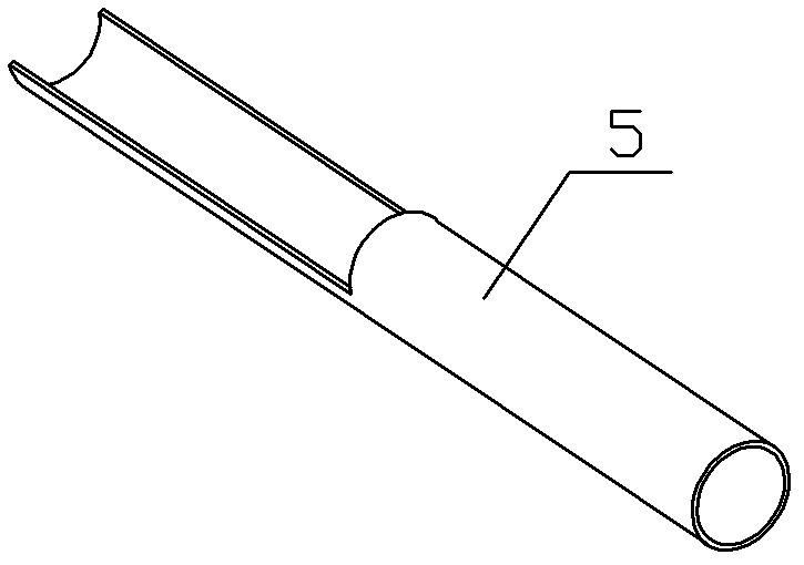
The invention discloses a process and device for flue gas wet desulphurization by using carbide slag or white clay as desulfurizing agent, and belongs to the field of air pollution control. The wet desulphurization device comprises an absorption tower, a slurry pool and gypsum dehydration equipment, wherein a demisting layer, a spraying layer, a flue gas absorbing zone and a slurry tank are arranged in sequence from up down inside the absorption tower; the flue gas absorbing zone is provided with a flue gas inlet; the wet desulphurization device further comprises a separation tank in which a stirrer is arranged; the separation tank is communicated with the absorption tower through a drainage tube; the drainage tube is positioned below the flue gas inlet; the inlet end of the drainage tube is inclined upward and extends into the flue gas absorbing zone; a notch is formed at the part of the drainage tube in the flue gas absorbing zone and in parallel to the axial line of the drainage tube and forms an upward-opening recess; the lower part of the separation tank is communicated with the gypsum dehydration equipment; and the upper part of the separation tank is communicated with the slurry pool. The device is applied to flue gas wet desulphurization. The gypsum slurry is pretreated before dehydration, so that the gypsum layer separates from the solution layer and the colloidal substance layer, which increases the purity of gypsum, reduces the water content of gypsum and improves the quality of gypsum.

Description

technical field [0001] The invention relates to the technical control field of air pollution, in particular to a flue gas wet desulfurization process and device using calcium carbide slag or white mud as a desulfurizer. Background technique [0002] At present, hundreds of desulfurization technologies have been developed and applied at home and abroad. These desulfurization methods can be roughly divided into three categories: dry method, semi-dry method and wet method. Among them, the limestone-gypsum desulfurization process in the wet desulfurization process has the advantages of High desulfurization efficiency, good stability, and the by-product of desulfurization is gypsum, which can realize the resource utilization of desulfurization products, so it has been widely promoted. [0003] The limestone-gypsum desulfurization process accounts for about 90% of the total desulfurization units under construction and built in the world. The limestone-gypsum method uses natural l...

Claims


Application Information

Patent Timeline
IPC IPC(8): B01D53/80B01D53/50
Inventor 李泽清夏纯洁莫建松程常杰
Owner ZHEJIANG TIANLAN ENVIRONMENTAL PROTECTION TECH
Learn More