
Timing simulation system and method

A time series simulation and clock technology, applied in the direction of instruments, electrical digital data processing, sustainable buildings, etc., can solve problems such as high power consumption

Inactive Publication Date: 2014-08-20
HUIZHOU TCL MOBILE COMM CO LTD
View PDF2 Cites 1 Cited by
  • Summary
  • Abstract
  • Description
  • Claims
  • Application Information

AI Technical Summary

Problems solved by technology

[0008] Because of the problems in the above-mentioned known technologies, the purpose of the present invention is to provide a timing simulation system and method thereof, to solve the problems of the known technology simulation I 2 The problem of high power consumption caused by C leakage

Method used


Image

  • Timing simulation system and method
  • Timing simulation system and method
  • Timing simulation system and method

Examples


Embodiment Construction

[0042] Embodiments of the timing simulation system and method thereof according to the present invention will be described below with reference to related figures. For ease of understanding, the same components in the following embodiments are described with the same symbols.

[0043] Figure 5It is a block diagram of the timing simulation system of the present invention. In the figure, the timing simulation system 1 includes a processing unit 11 , a first communication unit 12 , a signal transmission unit 13 , a second communication unit 14 and a power supply 15 . The processing unit 11 is used for generating a first direction setting signal and a first digital signal. The first communication unit 12 is connected to the processing unit 11 and outputs a first digital signal according to the first direction setting signal. The signal transmission unit 13 is connected to the first communication unit 12, and the signal transmission unit 13 provides a sequence of data channels f...


PUM


Abstract

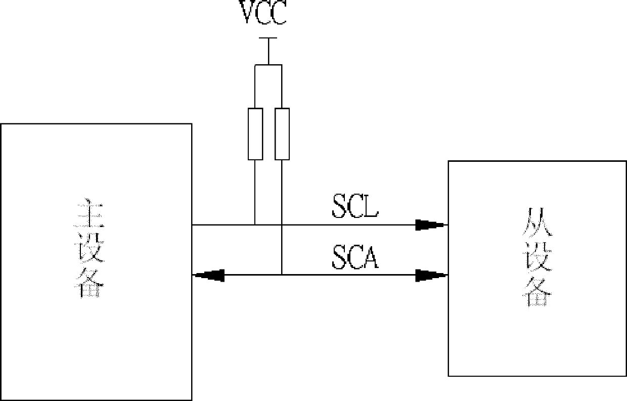
The invention discloses a timing simulation system and method. The timing simulation system is applied to the simulation of an internal integration circuit and comprises a processing unit, a first communication unit, a second communication unit, a signal transmission unit and a power supply. According to the invention, a high-impedance load is arranged on an I2C bus and then is connected to the power supply and the timing of an I2C is simulated by using software, thus the problem of I2C electric leakage can be improved, and the consumption of power is reduced.

Description

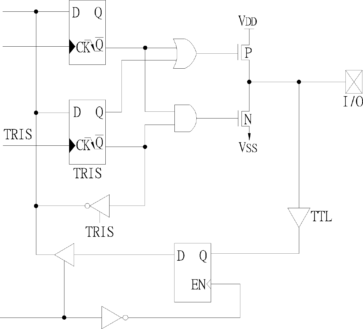
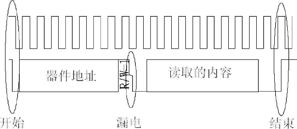
technical field [0001] The present invention relates to a timing simulation system and method thereof, especially to simulate an internal circuit for information exchange between a processing unit and peripheral equipment, so as to further increase the ports for information exchange between the processing unit and peripheral equipment and reduce power consumption. Background technique [0002] I 2 There are many C interfaces, but the dedicated I 2 The C interface is very limited, so two push-pull IO ports are commonly used to simulate I 2 C interface, and then through software simulation I 2 C timing, but there are certain problems in the traditional software simulation method, mainly because the considerable leakage current generated by the leakage will cause the jitter of the power supply, and the traditional I 2 C power consumption is higher. [0003] For the push-pull IO port, its structure is as follows figure 1 , The IO port is determined by the direction bit TRIS...

Claims


Application Information

Patent Timeline
Patent Type & Authority Patents(China)
IPC IPC(8): G06F13/38
CPCY02B60/1228Y02B60/1235Y02D10/00
Inventor 顾建良顾瞻
Owner HUIZHOU TCL MOBILE COMM CO LTD
Learn More