Bainite/martensite steel rail with 1,500 Mpa level of high toughness and manufacturing method thereof
A bainite and martensite technology, applied in the field of bainite/martensitic rail and its manufacturing, can solve the problem of difficulty in realizing the rail, and achieve the effect of excellent plasticity
- Summary
- Abstract
- Description
- Claims
- Application Information
AI Technical Summary
Problems solved by technology
Method used
Image
Examples
Embodiment 1
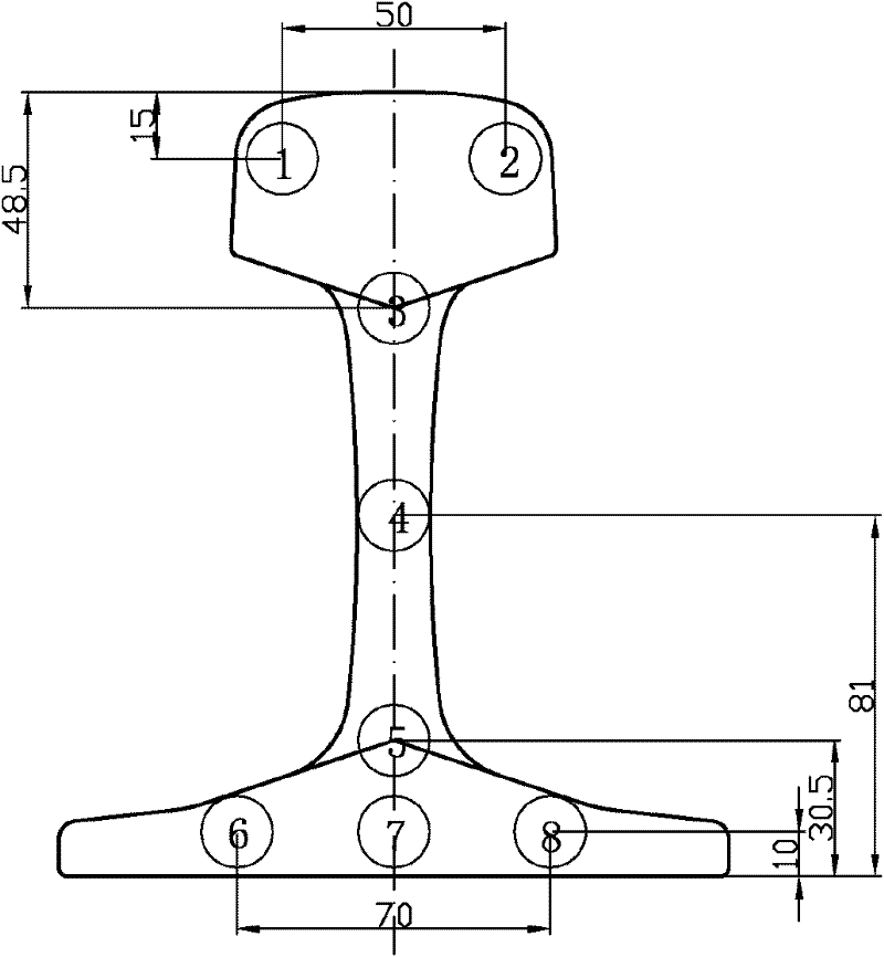
[0056] The following table 1-1 is the chemical composition and corresponding process conditions (cooling and heat treatment conditions) of the embodiment 1 of the rail of the present invention and the comparison rail, wherein the chemical composition refers to the composition and content of each element of the steel, and the balance is Fe and unavoidable impurities. The tempering heating temperature and tempering heating time in Example 1 refer to the tempering temperature and holding time of the entire section of the rail head after heating and cooling.
[0057] Chemical composition and process conditions of the steel rail of Table 1-1 embodiment 1 and the steel rail of comparative example
[0058]
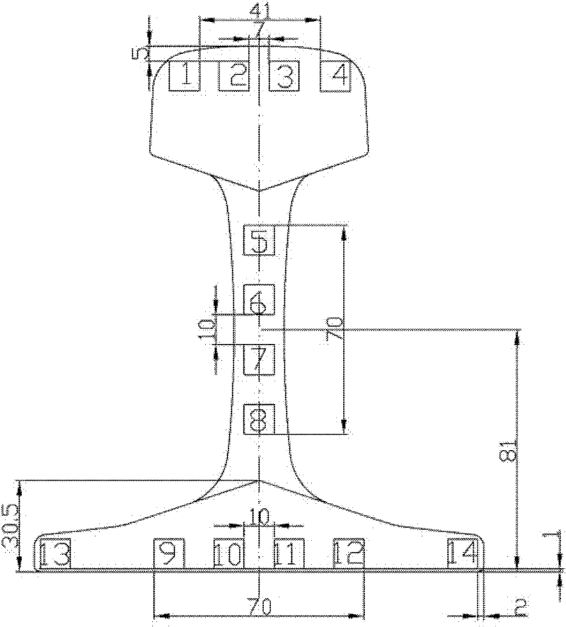
[0059] The comparison of the test results of the examples and the comparative examples are respectively shown in the following figures. Wherein, Table 1-2 is the full-section tensile test result of the steel rail of the present invention; Table 1-3 is the full-section impact ...
Embodiment 2
[0077] Similar to the above-mentioned Example 1, Table 2-1 shows the chemical composition and corresponding process conditions of the rail of the present invention in Example 1 and the comparison rail. In Example 2, the rail head was austenitized by reheating before accelerated cooling, and the tempering temperatures for Example 2 shown in Table 2-1 refer to when the rail head is heated, the rail waist and rail The tempering temperature range to which the bottom is heated at a speed of 3-10°C / s.
[0078] Table 2-1 The chemical composition and process conditions of the steel rail of the present invention and the comparative steel rail
[0079]
[0080] Similarly, table 2-2 is the tensile test result of the rail full section of embodiment 2; Table 2-3 is the rail full section impact performance test result of embodiment 2; Table 2-4 is the rail of embodiment 2 and pearlescent Comparison of the rail head tensile test results of the comparative example of the body shape; Table...
Embodiment 3
[0092] Similar to the above-mentioned embodiment, through multiple tables and combining Figure 8 and 9 To illustrate the improvement of Example 3 of the present invention compared to the rail of the comparative example. Table 3-1 shows the chemical composition and process conditions (heat treatment and cooling conditions) of the rails of Example 3 and the rails of Comparative Example. Table 3-2 shows the rail head tensile test results of Example 3. Table 3-3 shows the test results of the rail head impact performance of Example 3. Table 3-4 is the comparison of the rail head tensile test results of the rail of Example 3 and the rail head of the pearlitic comparative example. Table 3-5 is the comparison of the rail head impact performance of the rail of Example 3 and the rail head of Comparative Example. Figure 8 Shown is the result of the hardness test of the cross-section of the rail head in Example 2. Figure 9 The metallographic structure diagram of the rail head of E...
PUM
| Property | Measurement | Unit |
|---|---|---|
| Hardness | aaaaa | aaaaa |
| Hardness | aaaaa | aaaaa |
Abstract
Description
Claims
Application Information
 - R&D
- Intellectual Property
- Life Sciences
- Materials
- Tech Scout
- Unparalleled Data Quality
- Higher Quality Content
- 60% Fewer Hallucinations
Browse by: Latest US Patents, China's latest patents, Technical Efficacy Thesaurus, Application Domain, Technology Topic, Popular Technical Reports.
© 2025 PatSnap. All rights reserved.Legal|Privacy policy|Modern Slavery Act Transparency Statement|Sitemap|About US| Contact US: help@patsnap.com


