Compound type pneumatic non-contact gas claw
A non-contact and composite technology, applied in the field of composite pneumatic non-contact air gripper and non-contact handling air gripper, can solve the problems of unsatisfactory technology, excessive shear force, poor adjustability, etc. Detachable and replaceable, reducing the hoop shear force, the effect of stable adsorption
- Summary
- Abstract
- Description
- Claims
- Application Information
AI Technical Summary
Problems solved by technology
Method used
Image
Examples
Embodiment Construction
[0028] Embodiments of the present invention will be described in further detail below in conjunction with the accompanying drawings.
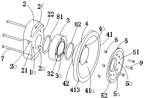
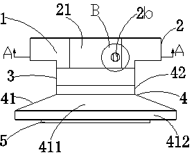
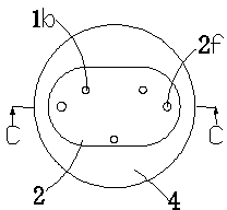
[0029] Figures 1 to 8 It is a structural schematic diagram of the present invention.
[0030] The reference signs therein are: air claw housing 1, installation through hole 1b, air claw top cover 2, cylindrical concave cavity 2a, air inlet hole 2b, longitudinal rectangular hole 2c, outwardly convex arc-shaped hole 2d, circular Countersunk hole 2e, mounting hole 2f, rectangular front face 21, boss press-fitting surface 22, middle part of air gripper 3, swivel cavity 3a, upper groove 31, lower groove 32, bottom suction cup 4, internal thread hole 4a , disc body 41, circular suction cup cavity 41a, arc transition cavity 41b, tapered torus 411, hat brim right-angled ring edge 412, hat brim annular bottom surface 413, cylinder 42, column chamber section 42a, diverter ring 5, Grab through hole 5a, pressurized small hole 5b, positioning counterbore...
PUM
 Abstract
Description
Claims
Application Information
 - R&D
- Intellectual Property
- Life Sciences
- Materials
- Tech Scout
- Unparalleled Data Quality
- Higher Quality Content
- 60% Fewer Hallucinations
Browse by: Latest US Patents, China's latest patents, Technical Efficacy Thesaurus, Application Domain, Technology Topic, Popular Technical Reports.
© 2025 PatSnap. All rights reserved.Legal|Privacy policy|Modern Slavery Act Transparency Statement|Sitemap|About US| Contact US: help@patsnap.com


