
Compound type pneumatic non-contact gas claw

A non-contact, composite technology, applied in the field of composite pneumatic non-contact air grippers, non-contact handling grippers, can solve the problems of unsatisfactory technology, poor adjustability, excessive shear force, etc., and achieve strong Detachable and replaceable, stable adsorption, and the effect of reducing hoop shear force

Inactive Publication Date: 2012-07-04
NINGBO UNIV
View PDF4 Cites 10 Cited by
  • Summary
  • Abstract
  • Description
  • Claims
  • Application Information

AI Technical Summary

Problems solved by technology

However, the non-contact conveying mechanism in the prior art still generally has defects such as large air consumption, small adsorption force, unstable adsorption, excessive shear force, and poor adjustability, so it is not ideal technically and cannot better meet production needs

Method used


Image

  • Compound type pneumatic non-contact gas claw
  • Compound type pneumatic non-contact gas claw
  • Compound type pneumatic non-contact gas claw

Examples


Embodiment Construction

[0028] Embodiments of the present invention will be described in further detail below in conjunction with the accompanying drawings.

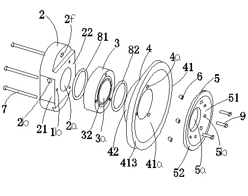
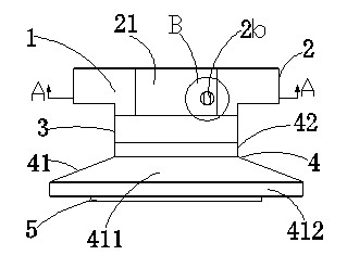
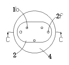
[0029] Figures 1 to 8 It is a structural schematic diagram of the present invention.

[0030] The reference signs therein are: air claw housing 1, installation through hole 1b, air claw top cover 2, cylindrical concave cavity 2a, air inlet hole 2b, longitudinal rectangular hole 2c, outwardly convex arc-shaped hole 2d, circular Countersunk hole 2e, mounting hole 2f, rectangular front face 21, boss press-fitting surface 22, middle part of air gripper 3, swivel cavity 3a, upper groove 31, lower groove 32, bottom suction cup 4, internal thread hole 4a , disc body 41, circular suction cup cavity 41a, arc transition cavity 41b, tapered torus 411, hat brim right-angled ring edge 412, hat brim annular bottom surface 413, cylinder 42, column chamber section 42a, diverter ring 5, Grab through hole 5a, pressurized small hole 5b, positioning counterbore...


PUM


Abstract

The invention discloses a compound type pneumatic non-contact gas claw which comprises a gas claw casing and a shunting ring, wherein the gas claw casing is provided with a downwardly opening cylinder cavity; a workpiece grabbing through hole is formed at the center of the shunting ring; the gas claw casing includes a gas claw top cover, a gas claw middle part and a bottom sucking disc, which are detachably and hermetically connected; the gas claw top cover is provided with a gas inlet communicated with the cylinder cavity; the gas claw middle part is provided with a rotary reflux cavity forming the main body section of the cylinder cavity; the bottom sucking disc is provided with a circular sucking disc concave cavity communicated with the cylinder cavity; the shunting ring is in clearance sleeve in the circular sucking disc concave cavity; an annular clearance gas injection channel is defined by the back side of the shunting ring and the cambered curve of the bottom wall of the circular sucking disc concave cavity; three groups of small pressurizing holes surrounding the grabbing through hole are uniformly distributed on the shunting ring in an equal-radian manner; a workpiece to be grabbed is suspended in front of the grabbing through hole to achieve the dynamic balance and the non-contact grabbing and handing functions under the combined action of negative pressure generated at the high pressure gas rotary reflux center, positive pressure generated in high pressure gas overflowing out of the annular clearance gas injection channel and the self-weight of the workpiece.

Description

technical field [0001] The invention relates to the technical field of handling and grabbing of high-precision thin slices, in particular to the technology of non-contact handling claws, in particular to the composite pneumatic non-contact claws of swirling flow and Bernoulli principle. Background technique [0002] With the development of manufacturing technology in the information industry, the size of liquid crystal glass substrates and polysilicon wafers has become larger and larger. In the traditional handling technology, due to the contact between the glass substrate and the roller, and the chip and the suction cup, the surface of the glass substrate and the chip will inevitably be damaged, which will affect the quality of the product, resulting in a high defective rate. In order to overcome the shortcomings of traditional handling technology, the current mainstream technology is non-contact handling. However, the non-contact conveying mechanism in the prior art still...

Claims


Application Information

Patent Timeline
Patent Type & Authority Applications(China)
IPC IPC(8): B65G47/91B65G49/07
Inventor 梁冬泰路波许栋明李建强居晓峰林金伟
Owner NINGBO UNIV
Learn More