A thermodynamic cycle system using carbon dioxide as a cycle working medium

A circulating working medium and heater technology, which is applied in steam engine devices, machines/engines, mechanical equipment, etc., can solve problems such as poor thermodynamic properties, low waste heat recovery rate, flammability, etc., achieve good thermodynamic properties, and improve waste heat utilization rate, the effect of reducing the lower limit of temperature

Active Publication Date: 2015-10-28
INST OF MECHANICS - CHINESE ACAD OF SCI
View PDF7 Cites 0 Cited by
  • Summary
  • Abstract
  • Description
  • Claims
  • Application Information

AI Technical Summary

Problems solved by technology

At present, medium and high temperature waste heat can be recovered by using the traditional Rankine cycle with water as the working medium, but when the temperature of the heat source is lower than 350°C, most of the heat is used to heat the latent heat of water, the waste heat recovery rate is greatly reduced, and the waste heat temperature is lower than 250°C °C, it is not even possible to use steam turbines to generate electricity
This part of waste heat is basically wasted at present, but it accounts for 30% to 50% of the total waste heat resources, and the potential for recycling is very large
[0003] An effective way to recover low-grade waste heat resources is to use the Rankine cycle with low-boiling point working fluids. The low-boiling point working fluids currently used are mainly alkanes and freons. Alkanes mainly include straight-chain hydrocarbons and aromatic hydrocarbons , such as butane, isobutane, pentane, toluene, etc., which have good thermodynamic properties but are flammable. Once the working fluid leaks, there is a danger of explosion; Freon working fluids generally have good stability and Safety, but different types of freon working fluids have the characteristics of poor thermodynamic properties, poor thermal stability, and toxicity. At the same time, freon working fluids are generally unfriendly to the environment and expensive, so they are not suitable for large-scale use in industrial fields

Method used


Image

  • A thermodynamic cycle system using carbon dioxide as a cycle working medium

Examples


Embodiment Construction

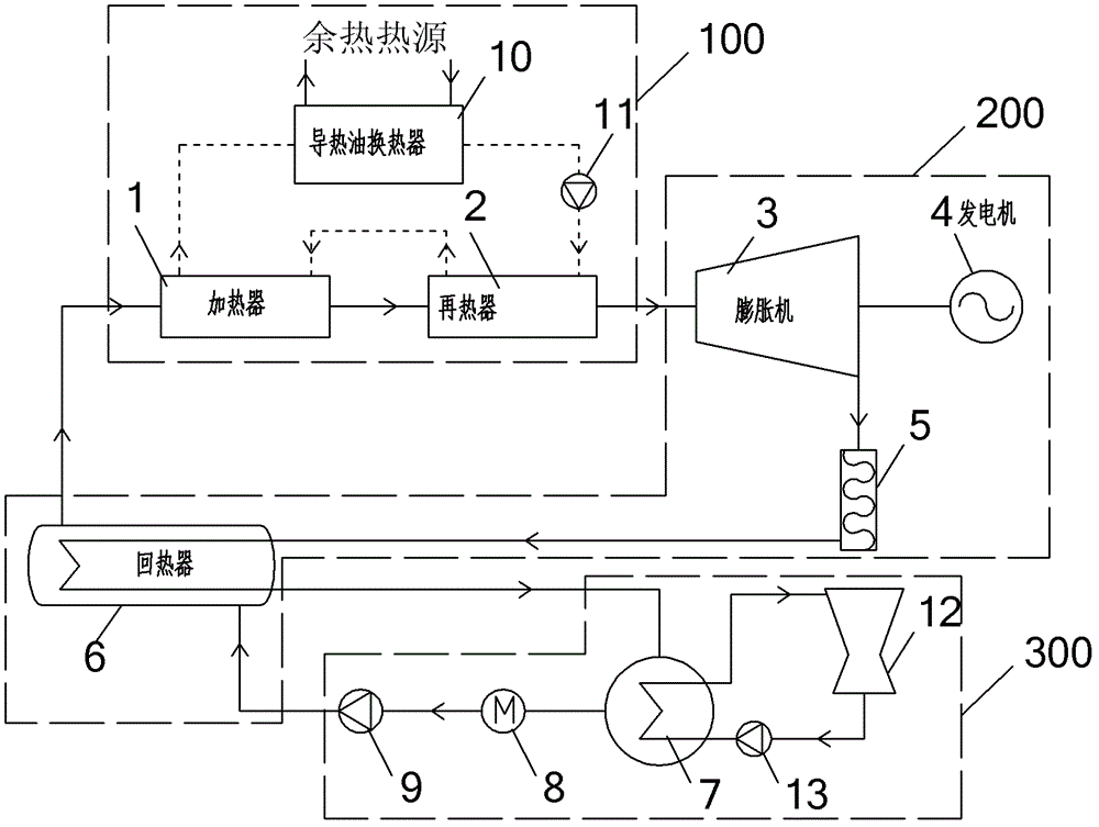
[0012] The present invention will be further described below with reference to the accompanying drawings.

[0013] Such as figure 1 Shown, the present invention is a kind of utilization CO 2 As a thermal cycle system for circulating working fluid, it is installed in the low-temperature waste heat environment widely present in the industrial field. Heater 1, heater 2, heat transfer oil heat exchanger 10 and heat oil pump 11 form heat recovery module 100, expander 3, generator 4, lubricating oil separation device 5 and regenerator 6 form expansion power generation module 200, condenser 7. A flow controller 8 , a working medium pump 9 , a cooling water tower 12 and a cooling water pump 13 form a condensation module 300 .

[0014] Heater 1, heater 2, expander 3, and lubricating oil separation device 5 are connected to the condenser 7 through the tube (shell) side of the regenerator 6, and the condenser 7, flow controller 8, and working medium pump 9 are reheated The shell (pipe...


PUM


Abstract

The invention discloses a thermal circulating system by utilizing carbon dioxide as a circulating working medium. The thermal circulating system comprises a heat recovery module, an expansion power-generating module and a condensation module, wherein an exhaust heat source exchanges low-temperature exhaust heat at 100-350 DEG C with a heat-conducting medium by the heat recovery module, the heat-conducting medium performs heat exchange with the circulating working medium by the heat recovery module again, the heated circulating working medium drives the expansion power-generating module to generate power, the circulating working medium is cooled in the condensation module after driving the expansion power-generating module to generate power and do work, and then is used in a circulating manner, and the circulating working medium is CO2. According to the invention, the lower limit of exhaust heat recycling temperature is reduced, the exhaust heat utilization rate is greatly improved and the unit energy consumption of an industrial product is reduced, therefore, the thermal circulating system is beneficial to saving energy and reducing emission.

Description

technical field [0001] The invention relates to the recovery and utilization of low-temperature waste heat in the industrial field and its power generation system, which relates to the technical field of waste heat recovery and power generation with low-temperature waste heat resources such as metallurgy, chemical industry, coal, ceramics, and building materials, and particularly relates to the use of CO 2 A thermodynamic cycle system in which a mixture thereof is used as a circulating working medium of a waste heat recovery system. Background technique [0002] The total amount of waste heat in the industrial field is huge. The total waste heat resources of metallurgy, chemical industry, coal and other industries account for 17% to 67% of their fuel consumption, and the recyclable waste heat resources are about 60% of the total waste heat resources. At present, medium and high temperature waste heat can be recovered by using the traditional Rankine cycle with water as the w...

Claims


Application Information

Patent Timeline
Patent Type & Authority Patents(China)
IPC IPC(8): F01K27/02F01K25/00
Inventor 李博魏小林李腾
Owner INST OF MECHANICS - CHINESE ACAD OF SCI
Why Eureka
Try Eureka