Eureka AIR delivers breakthrough ideas for toughest innovation challenges, trusted by R&D personnel around the world.

Fracture wound section stress measurement and control device

A stress measurement and control device technology, applied in the field of medical devices, can solve the problems of delayed fracture healing, small pressure, non-union, etc., and achieve the effects of dynamic control, high measurement and control accuracy, and small size

Inactive Publication Date: 2012-06-27
UNIV OF SHANGHAI FOR SCI & TECH
View PDF5 Cites 11 Cited by
  • Summary
  • Abstract
  • Description
  • Claims
  • Application Information

AI Technical Summary

Problems solved by technology

[0006] To sum up, the traditional method of external fixator-assisted treatment mainly has the following problems: First, the magnitude of the force applied to the fracture and trauma section cannot be accurately detected and controlled. , bone cell necrosis at the traumatic section, delayed fracture union, or even nonunion, if the pressure is too small, it will not achieve a certain level of stress stimulation and stable fixation; second, the process of adding force is all done manually by the doctor, and it cannot be achieved manually The third is that it is impossible to realize the real-time adjustment of the magnitude of the magnitude of the magnitude of the magnitude of the magnitude of the magnitude of the magnitude of the magnitude of the applied force, which can only be manually adjusted at a fixed stage, and there is no guarantee that the applied force will definitely promote the development of fracture healing towards a better level

Method used


Image

  • Fracture wound section stress measurement and control device
  • Fracture wound section stress measurement and control device
  • Fracture wound section stress measurement and control device

Examples


Embodiment Construction

[0041] The specific implementation of the present invention will be further described below in conjunction with the accompanying drawings and examples, but the protection scope of the present invention should not be limited thereby.

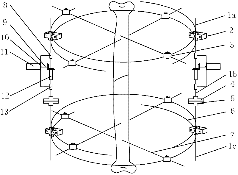
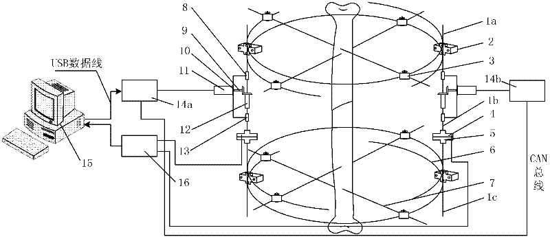
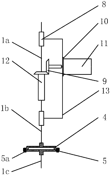
[0042] Such as Figure 1-11 As shown, a fracture trauma section stress measurement and control device includes a bone two-dimensional force sensor 4 (see Chinese patent CN 102138802A for details), an external bone fixation device, an automatic force control system, a data acquisition device and a computer. Wherein, the external bone fixation device includes support rods (upper support rod 1a and lower support rod 1c), the upper half and the lower half of the external bone fixation device respectively include two half-rings 6, and the half-rings 6 pass through the cross chuck 2 And it is integrated with the support rods 1a and 1c on both sides, the bone needle 7 passes through the broken bone and is fixed on the half ring 6 through the elastic nee...


PUM


Abstract

The invention discloses a fracture wound section stress measurement and control device based on a bone external fixing mode, which comprises a bone two-dimensional force sensor, a bone external fixing device, an automatic stress application control system and a computer. The bone two-dimensional force sensor is serially connected onto supporting rods on two sides of the bone external fixing device in a threaded manner so as to form a detecting system for the fracture wound section stress measurement and control device, the detecting system detects force exerted on the supporting rods, and accordingly stress applied to a fracture wound section is obtained via calculation and analysis; automatic stress application mechanisms are fastened on the supporting rods, the computer acquires detecting signals of the sensor, servo motor control signals are outputted by the computer via high-precision intelligent control algorithm so as to form the automatic stress application control system, and the stress applied to the fracture wound section is controlled by means of controlling a servo motor. The fracture wound section stress measurement and control device not only can meet requirements of fixation during fracture treatment, but also can realize real-time noninvasive detection of fracture wound section stress and dynamic stress control, and is small in volume, light in weight and high in measurement and control precision.

Description

technical field [0001] The invention relates to the field of medical devices, in particular to a stress measurement and control device for fracture and trauma sections based on external bone fixation. Background technique [0002] For a long time, delayed union and nonunion of fractures have been a difficult problem in clinical orthopedics. To reduce the occurrence of delayed union, fractures can be connected normally according to the law of healing. [0003] Fracture treatment usually includes three aspects: reduction, fixation, and functional exercise. The fixation of the broken bone during fracture healing has a very important impact on the treatment effect. Adjusting the stress distribution at the fracture site according to the requirements of different stages of the fracture healing period can promote the development of fracture healing towards the optimal level, so it is very important to rationally design fracture treatment devices. Because the bone tissue in the fra...

Claims


Application Information

Patent Timeline
IPC IPC(8): A61B5/22A61B17/66
Inventor 朱坚民李海伟黄之文王军毛得吉李付才
Owner UNIV OF SHANGHAI FOR SCI & TECH
Why Eureka
Eureka Blog
Learn More