
Ball end mill

A technology of ball end mills and end mills, which is applied in the direction of milling cutters, forming cutters, milling machine equipment, etc., can solve the problem of chip clogging, achieve the effect of suppressing the increase of resistance and load, and efficient cutting

Active Publication Date: 2014-07-16
MITSUBISHI MATERIALS CORP
View PDF5 Cites 0 Cited by
  • Summary
  • Abstract
  • Description
  • Claims
  • Application Information

AI Technical Summary

Problems solved by technology

Therefore, chips that are compressed and flow into the chip flutes as described above may be further compressed and cause chip clogging

Method used


Image

  • Ball end mill
  • Ball end mill
  • Ball end mill

Examples


Embodiment Construction

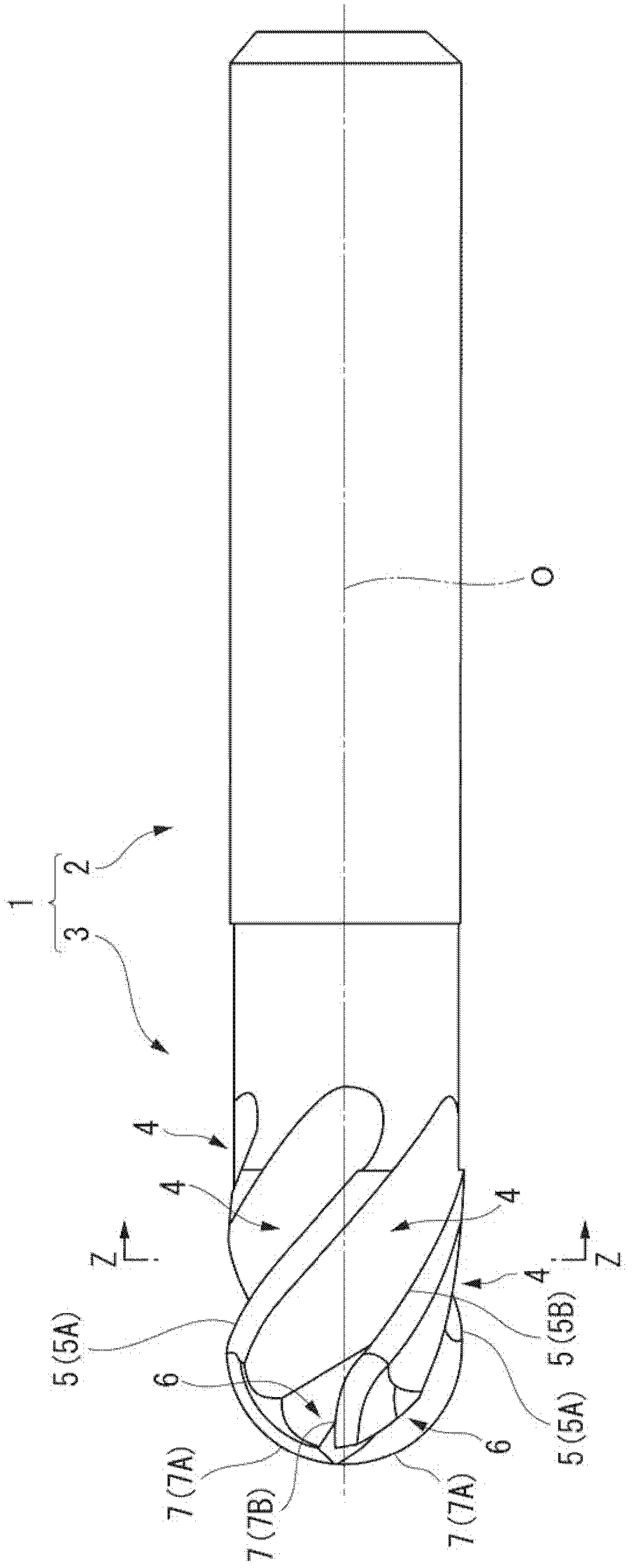
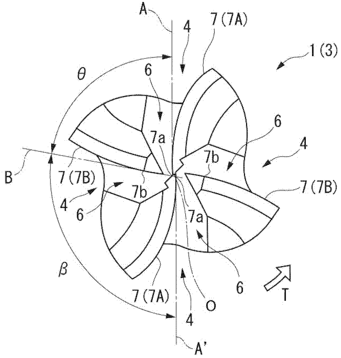
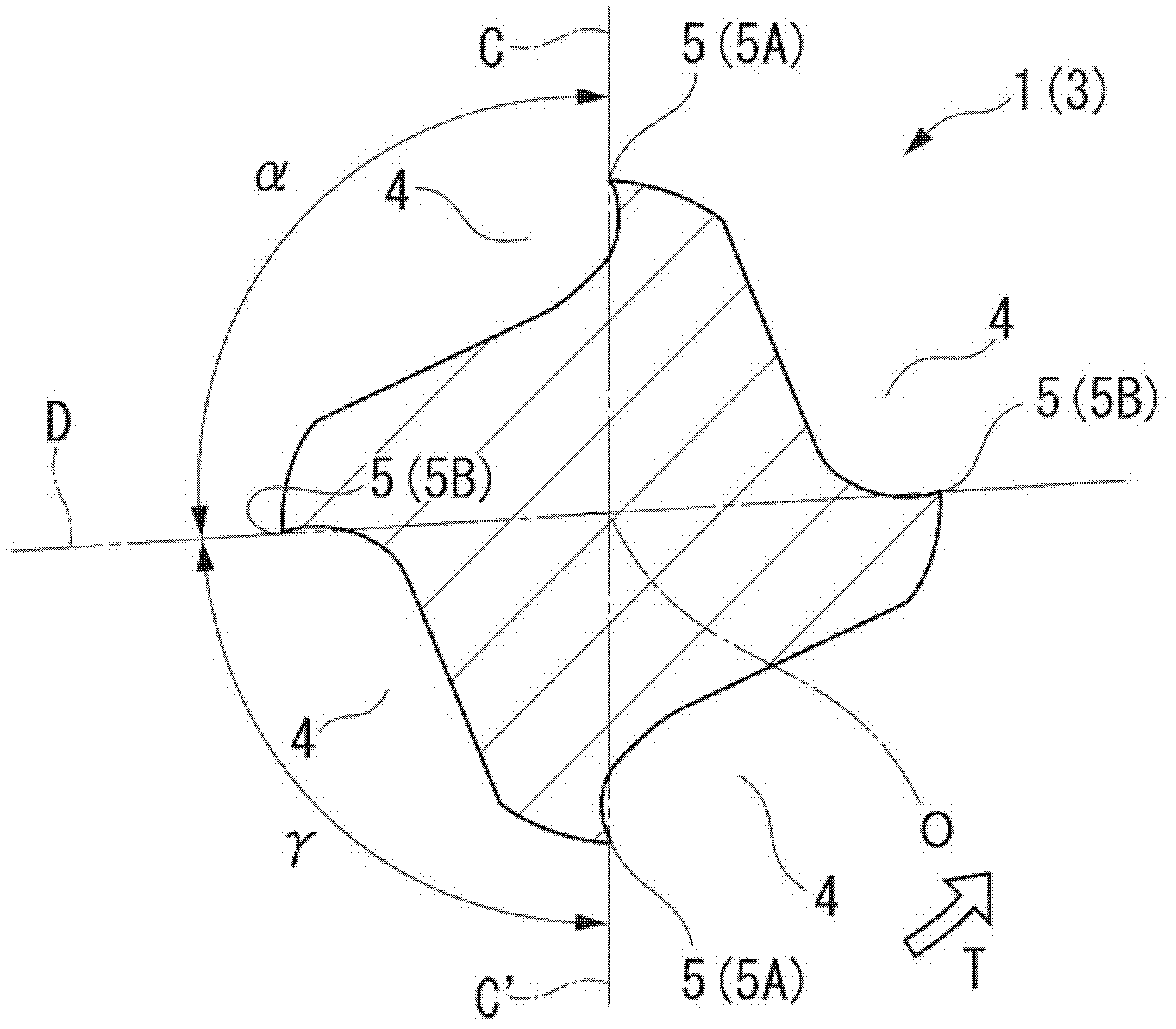
[0021] exist figure 1 , Figure 2A with Figure 2B In the illustrated embodiment of the present invention, the end mill body 1 is formed in a substantially cylindrical shape centered on the axis O. As shown in FIG. At the rear end of the end mill body 1 ( figure 1 The right side in the middle) is formed with a shank portion 2, and a cutting edge portion 3 is formed at the front end. The end mill body 1 is fed in a direction intersecting the axis O while being rotated in the rotation direction T around the axis O by mounting the shank portion 2 to the spindle of the machine tool, and is cut by the cutting edge portion 3 The material is cut. In addition, depending on the situation, while feeding in a direction intersecting the axis O, it also feeds in a direction along the axis O from the rear end of the end mill body 1 toward the front end, thereby also cutting the workpiece.

[0022] On the outer periphery of the cutting edge portion 3, a plurality of (four in this embodi...


PUM


Abstract

At the front end portion of the end mill body that rotates around the axis, a plurality of bottom cutting edges are formed extending from the inner side of the front end to the outer side of the rear end of the front end portion. On the outer peripheral portion of the end mill main body, a plurality of outer peripheral cutting edges connected to the outer end of the bottom cutting edge and extending toward the rear end are formed. Some of the plurality of bottom edges are long bottom edges extending from the vicinity of the axis at the front end portion of the end mill body. A straight line connecting the outer peripheral edge connected to the long bottom edge and the axis on any cross section perpendicular to the axis and a bottom edge positioned forward in the direction of rotation of the end mill compared with the long bottom edge The angle formed by the outer peripheral cutting edge and the straight line of the axis is greater than the tangent line on the inner end of the long bottom edge when viewed from the front end in the direction of the axis and the bottom of the long bottom edge located in front of the rotation direction of the end mill compared with the long bottom edge The angle formed by the tangent on the inner end of the edge.

Description

technical field [0001] this application claims priority based on Japanese Patent Application No. 2009-212128 for which it applied on September 14, 2009, and uses the content here. [0002] The present invention relates to a ball end mill, in which a plurality of hemispherical hemispherical bottom edges are formed at different intervals in the circumferential direction on the front end of the end mill body rotating around the axis . Background technique [0003] As such a ball end mill having cutting edges formed at unequal intervals in the circumferential direction, for example, Patent Document 1 proposes a ball end mill in which a plurality of peripheral cutting edges formed on the outer periphery of the end mill body Among them, the helix angle of at least one peripheral cutting edge is different from that of the other peripheral cutting edges, and an arc-shaped bottom cutting edge whose rotation trajectory forms a hemispherical shape is formed at the front end of the per...

Claims


Application Information

Patent Timeline
Patent Type & Authority Patents(China)
IPC IPC(8): B23C5/10
CPCB23C2210/282B23C5/1009Y10T407/1946Y10T407/1958B23C2210/0485Y10T407/1948
Inventor 畔上贵行
Owner MITSUBISHI MATERIALS CORP
Learn More