
Stable laser light source

A laser light source, stable technology, applied in the field of light source, can solve problems such as poor stability, achieve stable laser power, good turn-off performance, and good modulation performance

Active Publication Date: 2013-10-16
NANJING JILONG OPTICAL COMM
View PDF4 Cites 0 Cited by
  • Summary
  • Abstract
  • Description
  • Claims
  • Application Information

AI Technical Summary

Problems solved by technology

[0016] Among the above two types of laser light sources, the former has good modulation performance and poor stability

Method used


Image

  • Stable laser light source
  • Stable laser light source
  • Stable laser light source

Examples


Embodiment Construction

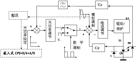
[0035] see image 3 As shown, a stable laser light source of the present invention includes a first adder, an optical power regulator, a bias circuit, an analog switch, a second adder, a first signal generator, a second signal generator, and a drive / protection circuit , Semiconductor laser tube LD, photoelectric tube PD, diode D, feedback coefficient K1f, K2f, low-pass filter.

[0036] The input end of the first adder is respectively connected to the optical power reference and the negative feedback end of the optical power. The optical power reference and the optical power feedback are added by the first adder and then enter the optical power regulator. The output terminal of the optical power regulator is connected to the first contact, the second contact is connected to the bias circuit, the first signal generator is connected to the control terminal of the analog switch, and the third contact is a common contact connected to the second adder One input terminal of the seco...


PUM


Abstract

The invention discloses a stable laser light source. Given optical power and fed-back optical power are added by an adder, and then the added optical power enters an optical power regulator. The output end of the optical power regulator is connected to one end of an analogue switch, and a biasing circuit is connected to the other end of the analogue switch. The analogue switch is controlled by a digital modulation signal. The common end of the analogue switch is connected to a second adder. One of the other two input ends of the second adder is connected with an analogue modulation end, and the other of the other two input ends of the second adder is connected with a current feedback end. The output of the second adder controls a semiconductor laser tube LD through a current regulator and a driving / protection circuit. The semiconductor laser tube LD serves as the current feedback end after passing through a feedback coefficient K2f. A diode D is connected in parallel with the two ends of the semiconductor laser tube LD. The cathode of a photoelectric tube PD serves as an optical power negative feedback end after passing through a feedback coefficient K1f. In digital modulation, first, second and third contact terminals of the analogue switch are turned on in turn; and in direct current or analogue modulation, the third contact terminal and the first contact terminal are turned on all the time. The stable laser light source has the advantages of high modulation performance, stable laser power and high turning-off performance.

Description

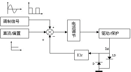
technical field [0001] The invention relates to a light source, in particular to a laser light source for measuring optical fiber communication device or equipment parameters. Background technique [0002] For laser light sources used to measure optical fiber communication devices or equipment parameters, the stability of optical power is one of the most important performance indicators. The well-known laser light source structure can generally be classified into two types: [0003] 1. Constant current drive laser light source structure, its principle is as follows figure 1 shown. [0004] The constant current drive laser light source is composed of signal generator, DC / bias circuit, adder, current regulator, drive / protection circuit, semiconductor laser tube LD, diode D, and feedback coefficient K1f. [0005] In the constant current driving laser light source, the "DC / bias" and the "modulation signal" sent by the signal generator are added together as the system setting,...

Claims


Application Information

Patent Timeline
Patent Type & Authority Patents(China)
IPC IPC(8): H01S5/068H01S5/00H01S3/13
Inventor 崔健吾
Owner NANJING JILONG OPTICAL COMM
Learn More