
Process for controlling machining deformation of L-shaped aluminum alloy thin-wall end frames

A technology for processing deformation and aluminum alloy, which is applied in the field of end frame processing of forgings or blanks, and can solve problems such as inability to guarantee use requirements, poor roundness, uneven wall thickness, etc.

Inactive Publication Date: 2012-06-13
HUBEI SANJIANG AEROSPACE GRP HONGYANG ELECTROMECHANICAL
View PDF5 Cites 11 Cited by
  • Summary
  • Abstract
  • Description
  • Claims
  • Application Information

AI Technical Summary

Problems solved by technology

[0008] The purpose of the present invention is to provide a turning method for processing and deforming L-shaped thin-walled end frames of aluminum alloy materials, so as to solve the problems of poor flatness, poor verticality, poor roundness, and uneven wall thickness in traditional turning methods, resulting in inability to guarantee Questions about usage requirements

Method used


Image

  • Process for controlling machining deformation of L-shaped aluminum alloy thin-wall end frames
  • Process for controlling machining deformation of L-shaped aluminum alloy thin-wall end frames
  • Process for controlling machining deformation of L-shaped aluminum alloy thin-wall end frames

Examples


example 1

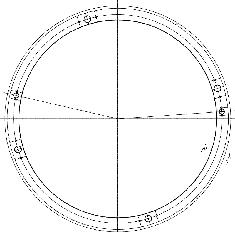
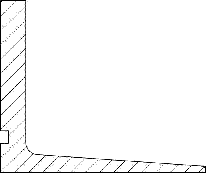
[0034] like figure 1 The typical part shown is the L-shaped aluminum alloy thin-walled end frame 4, and the blank is shown in the figure image 3 (die forging), the turning process is as follows:

[0035] Vertical lathe flat ends (rough datum)—horizontal lathe processing inner shape (rough and semi-finishing)—vertical lathe flat large end face (semi-finishing)—horizontal lathe processing inner shape to size (finishing)—vertical lathe Flat large end face (finishing).

[0036] 1) Rough datum machining of flat end faces of vertical lathe: install the parts to be processed on the vertical lathe, such as Figure 8 , 9 As shown, according to the total machining allowance of 5mm, the roundness of the part is corrected, and the roundness error of the correcting is Figure 10 As shown, it includes a baffle 1 and fastening bolts 2. The baffle 1 is fixed on the machine table 3 through the fastening bolts 2, and the baffle 1 squeezes the L-shaped aluminum alloy thin-walled end frame 4 ...

example 2

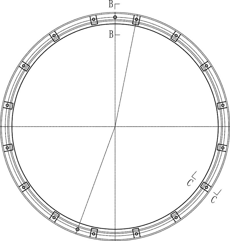
[0043] like image 3 The typical part shown is the L-shaped aluminum alloy thin-walled end frame, and the blank is shown in the figure Image 6 , 7 (die forgings), the turning process is as follows:

[0044] Vertical lathe flat ends (rough datum)—horizontal lathe processing inner shape (rough and semi-finishing)—vertical lathe flat large end face (semi-finishing)—horizontal lathe processing inner shape to size (finishing)—vertical lathe Flat large end face (finishing).

[0045] 1) Rough datum machining of flat end faces of vertical lathe: install the parts to be processed on the vertical lathe, such as Figure 8 , as shown in 9, according to the total machining allowance of 3mm, the roundness of the parts is corrected, and the roundness error of the correction is Figure 10 ; Control the extrusion deformation of the part <0.5mm; set an anti-rotation hole at the part that is subsequently processed by the blank of the part, and install an anti-rotation pin in the anti-rotation...


PUM


Abstract

A process for controlling machining deformation of L-shaped aluminum alloy thin-wall end frames belongs to a rotational part machining process and solves problems that service requirements cannot be guaranteed due to poor flatness, perpendicularity and roundness and uneven wall thickness of end frames machined in the existing machining process by the simple clamping mode according to reasonable cutting parameters. The process includes the step of lathing; the step of clamping by a vertical machine; and the step of clamping by a horizontal machine. By the process, the problems of poor flatness, perpendicularity and roundness and uneven wall thickness of the end frames machined by the conventional machining process are solved, quality of the end frames is improved and manufacturing cycle is shortened.

Description

technical field [0001] The invention belongs to the technical field of mechanical processing of revolving bodies, and in particular relates to a turning process method for controlling the processing deformation of an L-shaped thin-walled end frame of an aluminum alloy material, which is used for processing the end frame of a forging or a sheet blank. Background technique [0002] Aluminum alloy thin-walled frame parts are widely used in missile structural parts because of their light weight, material saving, and compact structure. Although aluminum alloy products have corrosion resistance, high specific strength and good machinability, compared with steel products, they have disadvantages such as poor rigidity (anti-deformation ability) and large linear expansion rate, which makes the processing of aluminum alloy thin-walled frame parts Afterwards, the shape and position error is large, it is difficult to guarantee the processing quality of the parts, and it is difficult to ...

Claims


Application Information

Patent Timeline
Patent Type & Authority Applications(China)
IPC IPC(8): B23B1/00
Inventor 谢萍
Owner HUBEI SANJIANG AEROSPACE GRP HONGYANG ELECTROMECHANICAL
Learn More