
Pupil function synthetic aperture imaging method

A technology of synthetic aperture and imaging method, which is applied in the field of optics, can solve problems such as phase synchronization, and achieve the effect of low difficulty and flexible method

Inactive Publication Date: 2012-06-06
XI'AN INST OF OPTICS & FINE MECHANICS - CHINESE ACAD OF SCI
View PDF0 Cites 4 Cited by
  • Summary
  • Abstract
  • Description
  • Claims
  • Application Information

AI Technical Summary

Problems solved by technology

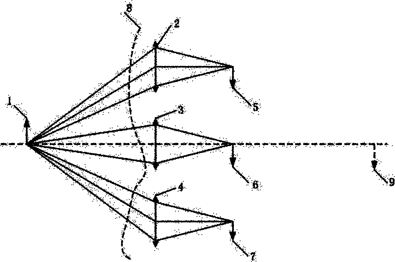
Regardless of the structural form, there will be a phase synchronization problem between each sub-mirror or each telescope, especially for visible light band and space-based synthetic aperture imaging, this problem is particularly prominent, if the phase synchronization accuracy requires wavelength One-tenth of that, then the visible light band requires an adjustment accuracy of tens of nanometers, which is undoubtedly a huge challenge for space-based systems

Method used


Image

  • Pupil function synthetic aperture imaging method
  • Pupil function synthetic aperture imaging method
  • Pupil function synthetic aperture imaging method

Examples


Embodiment 1

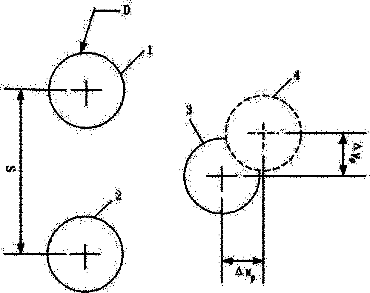
[0059] Such as figure 1 and figure 2 As shown, assuming a Golay-3 pupil distribution, the spacing between the sub-apertures S=1, the center coordinates of the Golay-3 pupil distribution is The diameter of the subaperture is D, and the expansion factor E of the pupil distribution is defined as:

[0060] E=s / D (1)

[0061] Detector pixel size dx per subaperture i =10μm, the focal length f of the sub-aperture imaging D =200mm, sampling number N=128, wavelength λ=0.5μm, sampling interval dx of a single sub-aperture p for:

[0062] dx p = λ f D d x i ( N - 1 ) - - - ( 2 )

[0063] ...


PUM


Abstract

The invention relates to a pupil function synthetic aperture imaging method, which comprises the following steps of: 1) acquiring complex amplitude distribution of an image surface; and 2) acquiring a synthetic aperture image according to the complex amplitude distribution of the image surface. According to the pupil function synthetic aperture imaging method, the adjustment difficulty is reduced, and imaging flexibility is realized.

Description

technical field [0001] The invention belongs to the field of optics, and relates to a synthetic aperture imaging method, in particular to a pupil function synthetic aperture imaging method. Background technique [0002] Space imaging technology requires higher resolution and sensitivity. For an earth observation telescope at the same height, the increase in resolution requires a proportional increase in aperture diameter; the increase in observation height requires a proportional increase in aperture diameter to maintain ground resolution increase; at the same time, the light-gathering ability of the system is proportional to the square of the aperture diameter, but increasing the aperture diameter means an increase in emission and processing costs, and empirically, the processing cost is approximately proportional to the cube of the aperture diameter. The diameter of the primary mirror of the Hubble Space Astronomical Telescope is 2.4 meters, resulting in a weight of 828 ki...

Claims


Application Information

Patent Timeline
IPC IPC(8): G02B27/58
Inventor 王建岗易红伟汶德胜李英才
Owner XI'AN INST OF OPTICS & FINE MECHANICS - CHINESE ACAD OF SCI
Learn More