Low-resistance chip resistor and manufacturing method thereof
A manufacturing method and technology of resistors, which are applied in resistor manufacturing, resistors, thick-film resistors, etc., can solve the problems of increased self-heating of resistors and damage of protective film printed wiring boards, and achieve high-precision manufacturing and enhanced electrical performance. The effect of durability
- Summary
- Abstract
- Description
- Claims
- Application Information
AI Technical Summary
Problems solved by technology
Method used
Image
Examples
Embodiment 1
[0048] Hereinafter, the structure of the low-resistance chip resistor of this invention is demonstrated.
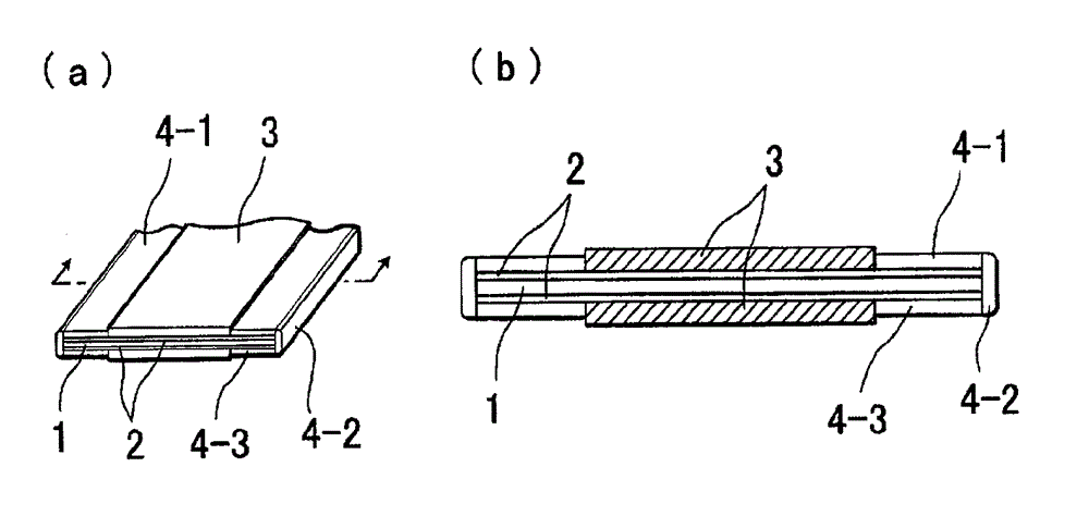
[0049] figure 1 (a) and (b) are a perspective view and a cross-sectional view of a long strip of an insulating substrate in which alumina powder, which is a type of ceramic powder, is dispersed in an epoxy resin at a volume ratio of 7:3. In these figures, metal plates made of iron-chromium-aluminum alloys, which are strip-shaped with a thickness of 0.05 mm and a width of 6.3 mm, and a length of about several meters, are laminated on several strip-shaped strips with a thickness of 0.3 mm and a width of 4.3 mm. The front and back sides of the substrate 1 of about m. A protective film 3 of epoxy resin with a thickness of about 10 μm is formed by screen printing in the long-dimension direction of the center of the upper and lower sides of the resistive film, and on the resistive layer 2 on both sides of the upper and lower protective film 3 1 and the end surface electrodes ...
Embodiment 1-1)
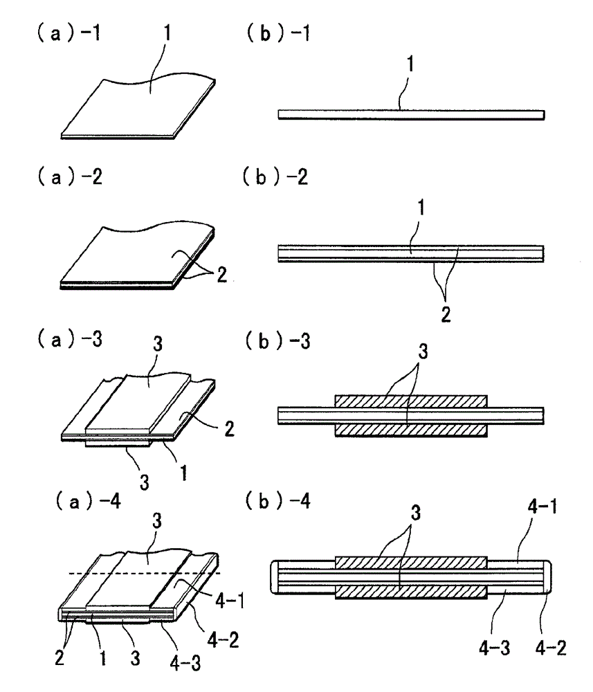
[0054] image 3 1 to 4 of (a) and (b) represent the above-mentioned Example 1 figure 1 A partial perspective view of the fabrication sequence of a low-resistance chip resistor and its cross-sectional view.
[0055] Figures (a)-1 and (b)-1 are insulating boards 1 in which alumina powder is dispersed and mixed in epoxy resin. The iron-chromium-aluminum alloy metal plate of the upper resistance layer is heated at 150°C to 200°C, and then press-rolled in the range of 2hPa to 3hPa, in (a)-3, (b)-3, and then up and down The above-mentioned epoxy resin is screen-printed in the central part, and baked at a temperature of 150°C to 250°C. In (a)-4 and (b)-4, the two ends are sequentially immersed in a chrome-nickel solution. Thereafter, baking is performed, and finally, as shown in (a)-4, cutting is carried out at intervals of, for example, 3.0 mm to 3.3 mm in width determined by a predetermined resistance value in a cross shape with respect to the longitudinal direction, and complete...
Embodiment 1-2)
[0057] Figure 4 The illustrated embodiment is a modified example of the above (Embodiment 1-1).
[0058] The difference between this embodiment and (Example 1-1) is that when the resistive film 2 is hot-rolled on the insulating substrate 1, the two ends are made stronger than the central part in the width direction, that is, the central part is 1.5hPa Pressure rolling was performed while pressure rolling was performed at 3 hPa on both sides.
PUM
 Abstract
Description
Claims
Application Information
 - R&D
- Intellectual Property
- Life Sciences
- Materials
- Tech Scout
- Unparalleled Data Quality
- Higher Quality Content
- 60% Fewer Hallucinations
Browse by: Latest US Patents, China's latest patents, Technical Efficacy Thesaurus, Application Domain, Technology Topic, Popular Technical Reports.
© 2025 PatSnap. All rights reserved.Legal|Privacy policy|Modern Slavery Act Transparency Statement|Sitemap|About US| Contact US: help@patsnap.com


