
Differential MEMS (Micro-electromechanical Systems) capacitive microphone and preparation method thereof

A condenser microphone and differential capacitor technology, applied in electrical components, electrostatic transducer microphones, sensors, etc., can solve the problems of increasing the noise of silicon microphones, limiting the overall noise level of silicon microphones, and achieving high microphone sensitivity and small air gap. , the effect of high microphone signal-to-noise ratio

Active Publication Date: 2012-05-16
SHANDONG GETTOP ACOUSTIC
View PDF7 Cites 20 Cited by
  • Summary
  • Abstract
  • Description
  • Claims
  • Application Information

AI Technical Summary

Problems solved by technology

The noise voltage brought by the high-voltage bias voltage will increase the noise of the overall silicon microphone. In a typical design, the noise contributed by the bias voltage accounts for more than 25% of the overall silicon microphone noise.
Therefore, the presence of bias voltage noise limits the noise level of the overall silicon microphone

Method used


Image

  • Differential MEMS (Micro-electromechanical Systems) capacitive microphone and preparation method thereof
  • Differential MEMS (Micro-electromechanical Systems) capacitive microphone and preparation method thereof
  • Differential MEMS (Micro-electromechanical Systems) capacitive microphone and preparation method thereof

Examples


Embodiment Construction

[0028] The following will clearly and completely describe the technical solutions in the embodiments of the present invention with reference to the accompanying drawings in the embodiments of the present invention. Obviously, the described embodiments are only some, not all, embodiments of the present invention. Based on the embodiments of the present invention, all other embodiments obtained by persons of ordinary skill in the art without making creative efforts belong to the protection scope of the present invention.

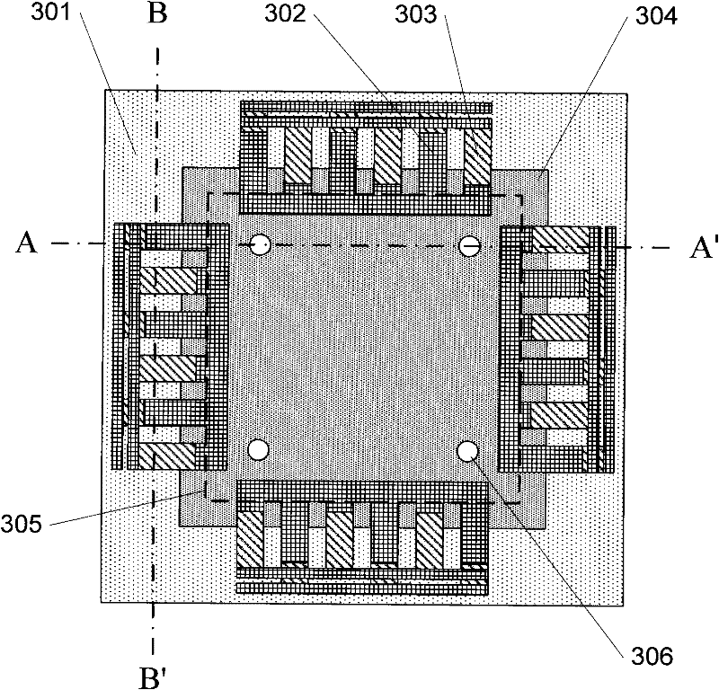
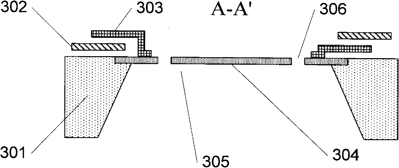
[0029] figure 1 It is a schematic diagram of a differential MEMS capacitive microphone according to an embodiment of the present invention, which includes: a substrate 301, a back cavity 305, an upper plate, a lower plate 302, a middle plate 303, a vibrating membrane 304, and a vibrating membrane 304 At least one opening 306 and a differential capacitance detection unit (not shown in the figure), wherein the edge of the vibrating membrane 304 is fixedly connec...


PUM


Abstract

The invention discloses a differential MEMS (Micro-electromechanical Systems) capacitive microphone and a preparation method for the microphone, wherein the capacitive microphone comprises a substrate, a back cavity, an upper electrode plate, a lower electrode plate, a middle electrode plate and a vibrating membrane. An edge of the vibrating membrane is fixedly connected onto the substrate, at least one open pore is arranged on the vibrating membrane, and the back cavity is arranged below the vibrating membrane; the middle electrode plate is arranged between the upper electrode plate and the lower electrode plate, a first capacitor is formed by the upper electrode plate and the middle electrode plate, and a second capacitor is formed by the lower electrode plate and the middle electrode plate; the middle electrode plate is fixedly connected onto the vibrating membrane and used for changing the position of the middle electrode plate when the vibrating membrane is vibrated along with a sound, so that capacitance values of the first capacitor and the second capacitor can be changed; and a differential capacitor pair is formed by the first capacitor and the second capacitor, and is used for an electric connection in a differential mode and can carry out gathering and processing for an electrical signal.

Description

technical field [0001] The present invention relates to micro-electromechanical systems (Micro-electromechanical Systems, MEMS) of silicon technology, in particular to a differential MEMS capacitive microphone and a preparation method thereof. Background technique [0002] The general silicon microphone design adopts the single-ended connection method, refer to the patent application: [0003] Patent application CN200480044734.4 discloses a silicon-based microphone element and its manufacturing method. The microphone sensing element has a diaphragm adjoining the perforated plate on each side and corner. The diaphragm is positioned over one or more back holes formed in the conductive substrate, wherein the back holes are smaller than the width of the diaphragm. A perforated plate is suspended over the air holes above the substrate. The diaphragm is supported by mechanical springs having two ends attached to the corners, sides or center of the perforated plate and terminati...

Claims


Application Information

Patent Timeline
IPC IPC(8): H04R19/04H04R31/00
Inventor 杨少军
Owner SHANDONG GETTOP ACOUSTIC
Learn More