
Imaging forming device

一种图像、图像数据的技术,应用在图像形成装置领域,能够解决不能满足用户需要、不可能实现输出处理等问题,达到缩短处理时间、实现输出处理的效果

Active Publication Date: 2012-05-16
SHARP KK
View PDF4 Cites 3 Cited by
  • Summary
  • Abstract
  • Description
  • Claims
  • Application Information

AI Technical Summary

Problems solved by technology

[0010] However, as in the technology disclosed in Patent Document 1, in an image forming apparatus having a function of displaying a preview of an image to be output so that the user can check it, the output process can be started only after the user confirms the completion of the image before output
That is, there has been a problem that it is impossible to realize output processing that matches the intention of a user (a user who values ​​speed) who wishes to omit the checking work before output, and thus cannot satisfy the user's needs.

Method used


Image

  • Imaging forming device
  • Imaging forming device
  • Imaging forming device

Examples


no. 1 example

[0085] Embodiments of the present invention will be described below with reference to the accompanying drawings.

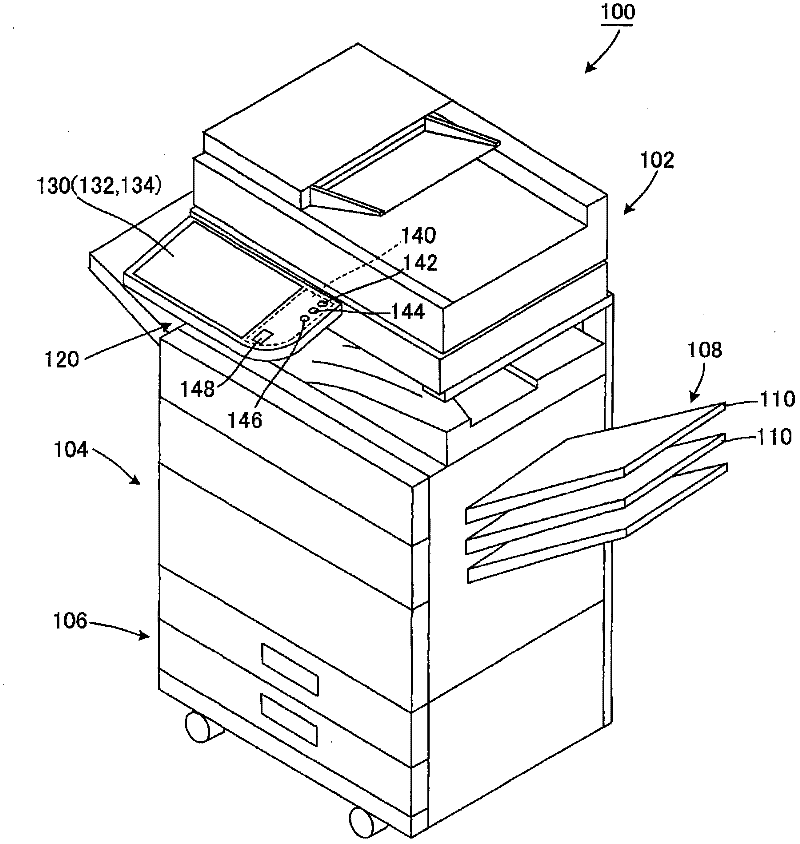
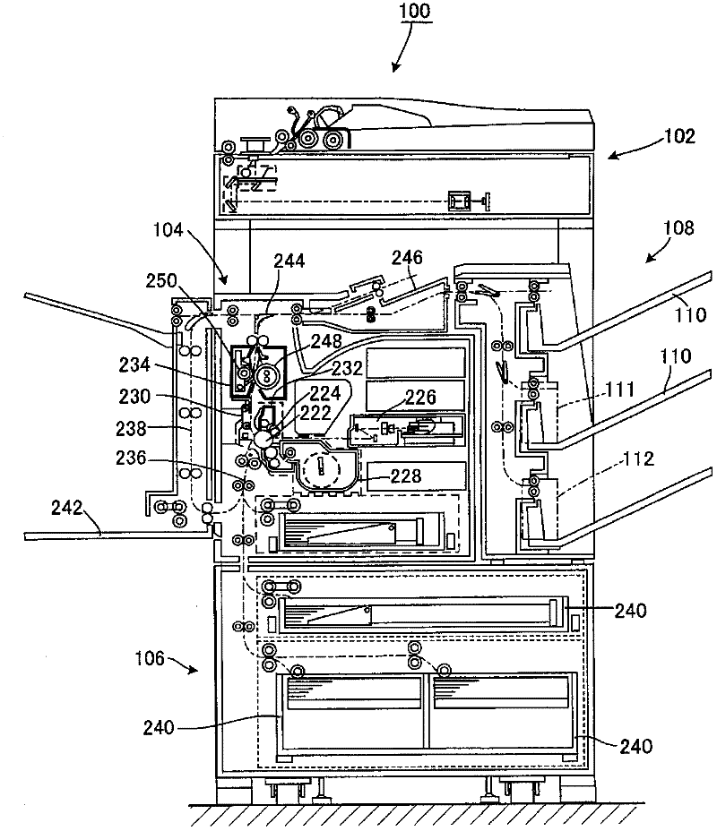
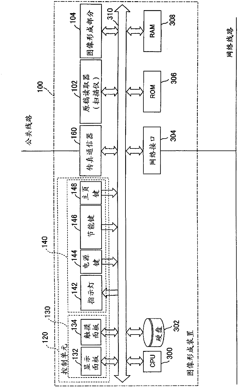
[0086] figure 1 is an explanatory diagram of one exemplary mode of carrying out the present invention, showing the overall configuration of the image forming apparatus according to the embodiment of the present invention. figure 2 It is an explanatory diagram schematically showing the internal mechanism of the image forming apparatus. image 3 is a functional block diagram showing the hardware configuration of the image forming apparatus. Figure 4 It is an explanatory diagram showing a preview display area on the touch-panel display of the image forming apparatus. Figure 5 It is an explanatory diagram showing an example of a screen displayed on the touch panel display. Image 6 is an explanatory diagram showing a state in which the preview area being displayed on the touch panel display is modified.

[0087] The image forming apparatus 100 according to an e...

no. 2 example

[0313] will refer to Figures 26 to 41 A second embodiment of the present invention is described. Since the second embodiment differs from the first embodiment only in the configuration of the control unit side controller, the description will focus on the difference of the control unit side controller. Furthermore, in the following description, the same components as those in the first embodiment are assigned the same reference numerals without description.

[0314] like Figure 26 As shown in , the control unit side controller 131B of this embodiment has: a preview display function for displaying multiple pages of original images in a preview form on the display panel 132; a movable display function for displaying multiple pages of original images in a movable manner and an input state guidance function for displaying the input state of image data input through the document reader 102 on the display panel 132 to guide the user.

[0315] The control unit side controller 13...


PUM


Abstract

An image forming apparatus includes a document reader, a storage for storing image data, an image output unit and a control unit. The control unit includes a display image generator for generating a display image, a display panel and a control unit-side controller having a function of presenting the display image based on the image data input in a preview representation and an output processing function of implementing an output process. As the output processing function, two schemes are provided: a first output scheme wherein, when image data has been input through the input unit, the images are output after displaying the images to be output in a preview representation on a display panel, and a second output scheme wherein, when image data has been input through the input unit, the image is directly output without displaying the image to be output in a preview representation on the display panel.

Description

technical field [0001] The present invention relates to an image forming apparatus such as a copying machine, a printer, a facsimile machine, and more particularly, an image forming apparatus equipped with an image display control device capable of displaying a plurality of pages of a document image in a preview form. Background technique [0002] Recently, an image forming apparatus including an image display control device capable of displaying a plurality of pages of a document image in a preview form is known. In this image forming apparatus, it is possible to confirm a scanned document before printing it out by displaying the processing result of the scanned (pre-scanned) document before executing a job. [0003] As an example of the prior art, there has been disclosed an image forming apparatus configured to scan a document and then perform image processing on the scanned document image, thereby outputting a printed document (see Patent Document 1). [0004] According...

Claims


Application Information

Patent Timeline
Patent Type & Authority Applications(China)
IPC IPC(8): H04N1/00
CPCH04N2201/3288H04N1/00H04N1/00427H04N1/00469H04N1/00424H04N1/00482H04N1/00448H04N1/00503H04N1/00411H04N1/00474H04N1/00458H04N2201/0094
Inventor 吉田真由子远木晋作
Owner SHARP KK
Learn More