Method for testing high-voltage power supply and power distribution system loop

A technology for power supply and distribution system and loop testing, which is applied in the direction of measuring electricity, measuring devices, measuring electrical variables, etc., can solve the problems of destroying high-voltage equipment, error-prone wiring, and increased workload, etc., and achieves simple testing devices and testing methods. Ease of use and reduced workload

Active Publication Date: 2012-05-16
CHINA MCC20 GRP CORP
View PDF3 Cites 6 Cited by
  • Summary
  • Abstract
  • Description
  • Claims
  • Application Information

AI Technical Summary

Problems solved by technology

But because this part of the circuit is more complicated, such as the secondary circuit of PT, because the coils are connected to each other, the resistance value is close to zero, and the calibration line is very easy to make mistakes, and when the PT secondary circuit has a short circuit, it cannot be judged, so It is necessary to remove the wires during line calibration, which greatly increases the workload; in addition, according to the construction conditions on site, even if the line checking work is accurate, the secondary circuit line may become loose and fall off during the process of reorganizing and restoring the wiring of the panel box Even open circuit or short circuit, these may cause the power distribution system to fail to receive power, and even damage the high-voltage equipment and endanger personal safety
Therefore, to confirm the circuit of the entire power distribution system through the method of calibration line, not only the workload is heavy, but also there are many hidden dangers

Method used


Image

  • Method for testing high-voltage power supply and power distribution system loop
  • Method for testing high-voltage power supply and power distribution system loop
  • Method for testing high-voltage power supply and power distribution system loop

Examples


Embodiment Construction

[0038] 1. Preconditions: All installation work of the power distribution system, wiring and wiring, high-voltage relay protection, and insulation test are completed, and there is no other construction work on the power distribution system before power is received.

[0039] 2. Operation steps:

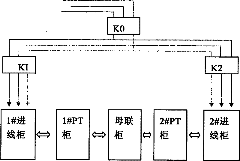
[0040] 1) Push the circuit breaker of the two-way incoming line cabinet to the working position; push the PT cabinet of the two sections of bus to the working position; push the bus tie lifting cabinet to the working position; pull the bus tie cabinet circuit breaker out of the cabinet, The upper and lower high-voltage contact baffles in the bus coupler cabinet are opened to expose the metal contacts.

[0041] 2) Press figure 1 Wiring shown: where K0, K1, K2 are three-phase air switches, A, B, C are three-phase 380V temporary test power supply.

[0042] 3) Measure the voltage value and phase sequence of the temporary power supply at K0, and ensure that the test power supply is in posi...


PUM


Abstract

The invention relates to a high-voltage control power transformation system, in particular to a method for testing a high-voltage power transmission and power distribution system. A method for testing a high-voltage power supply and power distribution system loop which comprises a busbar cabinet connected with a busbar PT (Potential Transformer) cabinet and a wire inlet cabinet at two sides, comprises the steps of: 1. knowing the electrical schematic diagram of the high-voltage power distribution system well, wherein the busbar PT cabinet comprises a No.1 PT cabinet and a No.2 PT cabinet, and the wire inlet cabinet comprises a No.1 wire inlet cabinet and a No.2 wire inlet cabinet; 2. introducing a way of an alternating current power supply to a self-made simple device; 3. feeding two ways of power supplies with the same phase sequence into two sections of inlet wires by the simple device; and 4. carrying out the related electrical test, comparing an analysis test result with a theoretical calculation value, and determining whether the circuit is correct. By the method for testing the high-voltage power supply and power distribution system loop, the problem in circuit loop can be rapidly found out without performing a high voltage test again.

Description

technical field [0001] The invention relates to a high-voltage control and transformation system, in particular to a test method for a high-voltage power transmission and distribution system. Background technique [0002] Before the high-voltage power supply and distribution system is officially powered on, it is necessary to check the primary and secondary circuits of the entire system. In the past, this work was basically done by calibrating the line. But because this part of the circuit is more complicated, such as the secondary circuit of PT, because the coils are connected to each other, the resistance value is close to zero, and the calibration line is very easy to make mistakes, and when the PT secondary circuit has a short circuit, it cannot be judged, so It is necessary to remove the wires during line calibration, which greatly increases the workload; in addition, according to the construction conditions on site, even if the line checking work is accurate, the secon...

Claims


Application Information

Patent Timeline
Patent Type & Authority Applications(China)
IPC IPC(8): G01R31/02
Inventor 刘民业沙德敏尹欣吴文平祃丽婷宋赛中
Owner CHINA MCC20 GRP CORP
Why Eureka
Try Eureka