
Direct current feed type motor testing system

A technology for motor testing and power feeding, applied in the direction of motor generator testing, etc., can solve the problems of power grid harmonic interference, complex control, and low control accuracy, and achieve the effect of reducing power supply capacity and improving system efficiency.

Inactive Publication Date: 2012-05-02
扬州华泰电子有限公司
View PDF3 Cites 8 Cited by
  • Summary
  • Abstract
  • Description
  • Claims
  • Application Information

AI Technical Summary

Problems solved by technology

The commonly used test platforms are basically absorbing energy from the power grid to supply the motor under test, and using a magnetic brake to adjust the torque of the motor under test. This method needs to absorb a large amount of electric energy from the power grid and consume energy with a magnetic brake. work in the same way, the control accuracy is low and a lot of energy is wasted
At present, some motor test platforms adopt the power feedback method, that is, the energy absorbed from the grid is provided to the motor under test, and at the same time, the energy of the motor under test can be fed back to the grid. However, this method requires the use of a grid synchronous inverter. The disadvantage of energy feedback to the grid is that when the energy is fed back to the grid, harmonic interference will be generated on the grid, which will affect the quality of the grid, and at the same time, the control is complicated and the cost is high

Method used


Image

  • Direct current feed type motor testing system
  • Direct current feed type motor testing system

Examples


Embodiment Construction

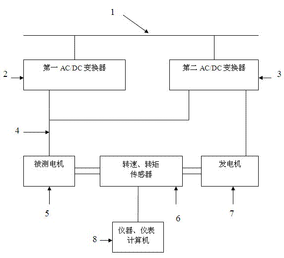
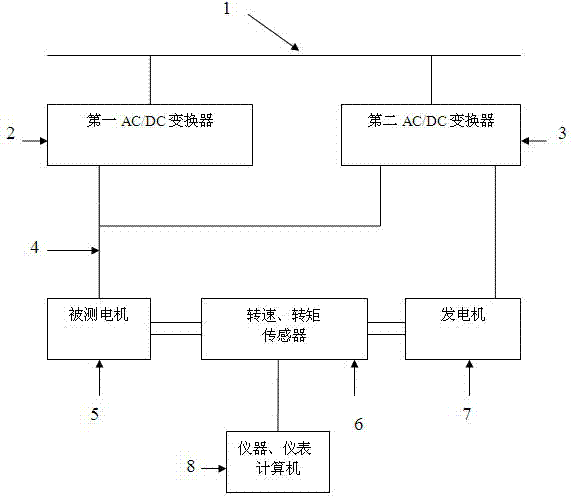
[0007] Such as figure 1 As shown, the present invention is at least provided with a first AC / DC converter 2 and a second AC / DC converter 3 , a generator 7 , and a rotational speed torque sensor 6 .

[0008] The input terminals of the first AC / DC converter 2 and the second AC / DC converter 3 are respectively connected to the grid AC input bus 1, and the DC output terminal of the first AC / DC converter 2 is connected to the DC of the motor 5 under test. Bus input 4.

[0009] The DC output terminal of the second AC / DC converter 3 is connected in series with the output terminal of the generator 7 to the DC bus input terminal 4 of the motor 5 under test.

[0010] The rotational speed and torque sensors 6 are coaxially connected between the tested motor 5 and the generator 7 through shaft couplings.

[0011] The signal output end of the rotational speed torque sensor 6 is connected to instruments, meters and a computer 8 for displaying various parameters of the motor under test.


PUM


Abstract

The invention relates to a direct current feed type motor testing system, belongs to the technical field of testing of motors and is used for measuring rotational speed, rotational moment, power, efficiency and other parameters of the tested motor. The direct current feed type motor testing system comprises at least two independent AC / DC (alternating current / direct current) converters, a direct current power generator and a rotational speed and rotational moment sensor. The inputs of the two independent AC / DC converters are respectively connected with an alternating current input busbar of a power grid, wherein the direct current side of one AC / DC converter is connected to a direct current busbar of the tested motor; and the direct current side of the other AC / DC converter is connected with the output of the direct current power generator in series and then connected to the direct current busbar of the tested motor, the output of the AC / DC converter is regulated to realize feedback of electric energy and regulation of the rotational moment of the tested motor, the overall power supply capacity of the system is reduced by utilizing the feedback energy and the efficiency of the system is improved.

Description

technical field [0001] The invention belongs to the technical field of motor testing, in particular to a high-efficiency and energy-saving motor testing and control method. Background technique [0002] The motor drive system is a very widely used component, and the technical parameter test of the motor is an important means to improve and verify the performance of the motor drive system. The commonly used test platforms are basically absorbing energy from the power grid to supply the motor under test, and using a magnetic brake to adjust the torque of the motor under test. This method needs to absorb a large amount of electric energy from the power grid and consume energy with a magnetic brake. Working in the same way, the control accuracy is low and a lot of energy is wasted. At present, some motor test platforms adopt the power feedback method, that is, the energy absorbed from the grid is provided to the motor under test, and at the same time, the energy of the motor un...

Claims


Application Information

Patent Timeline
Patent Type & Authority Applications(China)
IPC IPC(8): G01R31/34
Inventor 高从兵
Owner 扬州华泰电子有限公司
Learn More